There are a number of concepts to think through before we get into deploying Tanzu. Below outlines design guidelines and contextual thinking for the various patterns you will see within Tanzu and Kubernetes generally. If you’re new to this, concepts within Kubernetes are dense, and you can easily get overwhelmed. To help, I’ll try to provide links to official documentation where new concepts appear.
Hopefully, I will be able to slowly unpack things and make them easier to digest. I’ve personally found Kubernetes a gift that keeps on giving. There are endless possibilities and opportunities to learn new things at every corner.
I’m not attempting to rewrite the Kubernetes manual. If reading this article whets your appetite for more, I suggest heading over to Kubernetes.io to broaden your knowledge of the concepts. All of my understanding over the years has come from the main documentation portal, in response to my own curiosity or questions from my clients.
If you love learning about Kubernetes, I suggest playing with other distributions to gain deeper insight. Seeing the technology from other standpoints is very helpful for growth and clear thinking. Red Hat OpenShift Container Platform (or upstream OKD) and SUSE Rancher are both great distributions and are well worth the effort in learning.
Check out the following articles to see how things are deployed with NSX integrated Load Balancer. It’s also possible to deploy using VMware AVI Loadbalancer. For VLAN-only deployment, HA Proxy and VMware Foundation Load Balancer are also options.
Navigation
- Supervisor Cluster
- Namespaces
- Networking
- Egress
- Services
- Authentication
- DNS
- Certificates
- Secrets
- Container Registry
- Storage
- Network Policies
- Pod Security Standards
- Backup
- o11y (Observability)
- Conclusion
Supervisor Cluster
Tanzu’s foundation starts with what is called a supervisor cluster. This has a 1-1 relationship with a compute cluster in vSphere. In my lab, I only have a single node in the management domain with no workload domains, so placement is straightforward enough. For larger environments, you can selectively pick for management and/or workload domain compute clusters depending on the requirement. Just know that you can only have one supervisor per cluster.
The supervisor cluster is a Kubernetes (K8) cluster which is formed using templated OVA files from a dedicated Tanzu content library. Usually, there are at least three nodes in a cluster, but it’s also possible in VCF9 to deploy a single node for dev/test use cases. For production use, always deploy three. The supervisor runs a key-value database called etcd, which is built with quorum and leader election. Your three nodes will give you 100% of the votes, lose one, and you still retain quorum with 66.66% of the votes.
If you have the benefit of a larger physical platform, you can configure vSphere zones and spread the supervisor nodes across them. If you have, for example, a stretched cluster, then technically, the only supported route is a vSAN stretched cluster. Although it will also work using a VMware vSphere Metro Storage Cluster (vMSC) from your preferred vendor, Broadcom has yet to qualify anything but vSAN. You therefore run the risk of not getting production support.
I’ve deployed Tanzu on vMSC stretched clusters for financial institutions that have accepted this liability. In one case, we had a “soft qualification” from an ex-VMware Tanzu architect.
From an architectural point of view, both vSAN and, for example, NetApp Metro Cluster perform synchronous replication. At a high level, this means writes are committed to multiple fault domains (objects, arrays, drives, etc.) before confirming the success of the write back to the client. In other words, this means the recovery point objective is zero.
Ultimately, the supervisor is just virtual machines running software components (as containers) such as etcd and kube-api. Should a failure occur, vSphere HA will recover the virtual machines and the components within to a viable node, without data loss. The recovery time objective is measured by the time it takes for vSphere HA to restart the virtual machine. In my own business continuity testing with clients, the restart time is measured in minutes, not hours.
From this perspective, I personally see little difference between vSAN or storage vendor “X”, as long as the system is designed properly, including the relevant tier breakers/witness components to handle split-brain type scenarios, correct bandwidth, latency, data centre interconnect resiliency, etc.
When sizing the virtual machines for the supervisor, the main thing to note is that you can scale up the VM, but not down. Hence, the best starting place is arguably small or medium. Tiny is not recommended as an out-of-the-box install with all the default components. Tanzu will consume roughly 6GB of RAM, which doesn’t leave much headroom.
| vCPU | Memory (GB) | VM Class |
| 2 | 8 | tiny |
| 4 | 16 | small |
| 8 | 16 | medium |
| 16 | 32 | large |
Broadcom have a bunch of supervisor services which are available to deploy in the supervisor cluster. There is a GitHub page here, which is the main portfolio page. The manifests for each service are stored within the Broadcom support portal. Each supervisor service will deploy into its own namespace, with a domain ID suffix, i.e. domain-c10.
The supervisor services you definitely want to install / upgrade are:
- VKS Service – a service that allows the consumption of VKS clusters. See this interop matrix.
- Local Consumption Interface – see VKS objects inside vSphere
Ones worth playing with are below, check the GitHub page here for more information.
- Certificate Management Service – Cert Manager for issuing certs
- Cloud Native Registry Service – Harbor container registry
- ArgoCD – CI/CD capabilities for deploying VKS clusters and vSphere pods etc.
- Contour – Ingress controller for Kubernetes
vSphere Kubernetes Services
You can deploy containers from the supervisor cluster on bare metal (vSphere Pods) or a virtual machine-based vSphere Kubernetes Services (VKS) cluster. You can also mix and match as you see fit.
VKS clusters managed by a supervisor service called vSphere Kubernetes Service, this used to be called Tanzu Kubernetes Grid Service. With VCF 9.0.2 you can take the service all the way to version 3.6.0. This includes many more specifications to control how the VKS nodes themselves are deployed and configured. For example, deploying routable pods has changed quite a bit in the later versions, requiring different Kubernetes objects to control Antrea CNI, etc. Examples of these are shown in the other articles on Tanzu, here and here.
Containers orchestrated by the supervisor are called vSphere Pods. They are scheduled on bare metal ESX nodes through an interaction between the CRX container runtime and Spherelet on the ESX hosts, and kube-scheduler on the supervisor control plane nodes.
As a bonus Tanzu feature, you can also deploy virtual machines alongside containers by way of a “VirtualMachine” Kubernetes object. This allows you to create more nuanced microservices applications, where, for example, you use a virtual machine alongside containers. Perhaps the virtual machine runs drivers which are incompatible with containers. Or you want particular resource guarantees, compute resources for a database server, but still want containers for everything else. Having virtual machines in code will allow your developers to consume both in their code pipelines, which brings efficiency, better automation and less or perhaps no interaction with traditional infrastructure teams.
As a consumer of the supervisor, you have limited access to the Kubernetes API. The supervisor is a Broadcom opinionated Kubernetes distribution. You aren’t granted full cluster-admin rights. It’s possible to grant yourself cluster-admin via a backdoor if you’re running a test system. The example below, which you run from root on one of the supervisor nodes, will grant the AD group “Tanzu Administrators” cluster-admin rights. It does this through the use of the SSO integration between vSphere and the Supervisor.
cat << EOF | kubectl apply -f -
apiVersion: rbac.authorization.k8s.io/v1
kind: ClusterRoleBinding
metadata:
  name: wcp:group:aclab.uk:tanzu-administrators:cluster-admin
roleRef:
  apiGroup: rbac.authorization.k8s.io
  kind: ClusterRole
  name: cluster-admin
subjects:
- apiGroup: rbac.authorization.k8s.io
  kind: Group
  name: "sso:Tanzu Administrators@corp.aclab.uk"
EOF
Containers on a guest-based VKS cluster are scheduled within virtual machines running containerd as the runtime and a vanilla Kubelet agent. Guest clusters tie in to the supervisor for life cycle management, authentication, load balancing, storage provisioning, certificate management, amongst other things. To deploy a VKS cluster, you hand the supervisor a YAML file, to which it then spawns the guest cluster using ClusterAPI. Example files are available on GitHub for VPC and NSX Classic.
From the perspective of ClusterAPI, the supervisor is a “management cluster”, and the VKS clusters are “workload clusters”. The workload or VKS clusters are managed and orchestrated as “Cluster” objects in the management cluster; in a way, they are downstream or subordinate to the management cluster. You’ll see this when we get into the deployment in a later article.
VKS clusters are fully conformant Kubernetes clusters and, as such, you are granted full cluster-admin rights. They are still opinionated with a fair amount of VMware defaults, but less so, and are generally more flexible than the supervisor. However, for better or worse, containers are not scheduled on bare metal. Instead, they are scheduled within virtual machines.
Sizing for the VKS nodes is determined by the configuration of a vmClass specification within the YAML you send to the supervisor. Virtual machine classes are pre-determined by configuration options set within vSphere, which are under the control of the vSphere administrator. For an average deployment of VKS you would have three control plane nodes and at least two worker nodes.
The size of the control plane depends on how big your cluster will be, and also the specific requirements for any additional cluster services you add. Below outlines sizing guidelines for control plane nodes.
| Number of workers | vCPU | Memory (GB) | VM Class |
| 1-5 | 2 | 4 | small |
| 6-10 | 2 | 8 | medium |
| 11-100 | 4 | 16 | large |
| 101 to max of 150 | 8 | 30 | xlarge |
Sizing of the workers depends on what your application stacks look like and the requirements for each container. CPU/Memory requests and limit configurations, for example, Deployments or StatefulSets, play a part in calculating how big to make the workers. Additional components, such as service mesh, will also increase requirements.
Control plane nodes in VKS run a lighter set of components compared to the supervisor; they run on average around 1.5GB of resources per node vs 6GB. Together they form a unique “workload” Kubernetes cluster with the usual components such as Kubelet, etcd, kube-api and kube-scheduler. Worker nodes are lighter still; They run Kubelet agent, which interacts with kube-scheduler on the control plane nodes, in order to schedule workloads which you deploy. There is no quorum model for workers; pods are scheduled or not depending on standard Kubernetes scheduling logic. If a node fails, Kubernetes will try to automatically heal the application by scheduling new pods on surviving nodes.
Resource Management
Remember that when a node becomes constrained, it will likely start terminating pods (a pod is a bucket for 1 or more containers) to reclaim resources. Kubelet monitors resources such as memory, disk space and inodes. When thresholds are passed, proactive failure of pods will occur to keep the node functional. You can read the official document on this subject for more details.
Also worth knowing is the behaviour of the “Limit” flags for compute resources.
- Hit CPU limits cause throttling.
- Memory limits cause OOMKilled events, and pods will crash and restart.
- If you specify a limit without a request, the request will become the limit.
This is really worth remembering when writing code for your applications. More information is available on this subject here.
Namespaces
Namespaces within Tanzu supervisor clusters in the same vCenter instance must be unique and cannot be shared. For example, production and non-production supervisors cannot share a common namespace name. Each supervisor namespace contains the following:
- All the required supervisor Kubernetes objects to spawn VKS clusters using ClusterAPI.
- Scheduled vSphere Pods.
- Permissions for resource creation and associated VKS clusters.
- Storage class assignments for persistent volumes.
- Capacity and compute resource limits are controlled by DRS.
- Content Library associations.
- Virtual machine class associations for VM and VKS node creation.
Namespaces ring-fence resources, permissions and networking for different teams, business units, applications or environments. It’s normal practice to create multiple and associate-related groups of permissions to create isolation boundaries.
Below outlines some common approaches for namespace deployments. This is not an exhaustive list of all possibilities; additionally, combinations of the below models are also possible. Note, namespaces created within the Supervisor do not automatically apply to the VKS clusters. This is because each VKS cluster is its own Kubernetes cluster, with its own etcd database and control plane.
Single Namespace – Multiple Clusters
With this design, multiple VKS clusters are provisioned into a shared namespace. This is a simplified approach that shares all a global or common association of storage, permissions, resource limits, content libraries and virtual machine classes.
Although this is a simple route, it lacks the ability to easily constrain permissions between VKS clusters from vSphere. To achieve permission isolation, custom Kubernetes role bindings will need to be added to each VKS cluster to create full permission isolation. The customisation would not be deployed via vCenter, but rather through the individual Kubernetes API of each VKS cluster.
For the VKS cluster namespaces themselves, below outlines two common variations. Per team or per app namespaces. For each VKS namespace, either per app or per team, resource quotas can be applied to constrain what’s available to each team or application. Limit ranges can optionally be applied for sensible defaults where applications do not contain quotas.

Departmental Namespaces
In this example, each single VKS cluster or group of VKS clusters are groups into departmental namespaces. Associations of storage, permissions, resource limits, content libraries and virtual machine classes can be fully separated or consciously shared by selecting common attributes. Departmental permissions from vSphere are not constrained and can be easily configured in vSphere for VKS permission isolation.
For the VKS cluster namespaces themselves, namespaces are commonly created per application. Where applicable, resource quotas can be applied to constrain what’s available for each application. Limit ranges can optionally be applied for sensible defaults where applications do not contain quotas.

Environmental Namespaces
In this example, each single VKS cluster or group of VKS clusters are grouped into an environmental namespace. Associations of storage, permissions, resource limits, content libraries and virtual machine classes can be fully separated, or consciously shared by selecting common attributes. Environments are constrained and Tanzu admins can be easily configured in vSphere for permission isolation.
For the VKS cluster namespaces themselves, namespaces are commonly created per application or department. Where applicable, resource quotas can be applied to constrain what’s available to each application or department. Limit ranges can optionally be applied for sensible defaults where applications do not contain quotas.

Networking
Within VCF9 there are four principal ways to configure the supervisor and VKS networking. Within each there are variations depending on what load balancer you have or want to configure. The networking topology of each is quite different, hence I’ll unpack each core route in the sections that follow. Over time, I hope to produce further articles for each route.
- NSX VPC Networking
- With NSX load balancer – Deployment article.
- With AVI load balancer
- NSX Segment Networking (aka NSX Classic)
- With NSX load balancer – Deployment article.
- With AVI load balancer
- VDS Port Group Networking
- With NSX load balancer
- With AVI load balancer
- With VMware Foundation load balancer
- With HA Proxy
- Simplified Deployment
- With AVI load balancer
- With VMware Foundation load balancer
NSX VPC Networking
To deploy VPC networking with Tanzu, there are some rules and pointers for the base configurations. Some of these are unpacked later with diagrams.
- Tanzu with VPC only works with Centralised Transit Gateway.
- The associated edge cluster must be active/passive.
- To use active/active, you need to go down the NSX segment/classic route.
- You can associate the supervisor with the default project or another project as required. In my lab, I deployed the supervisor to the default system project.
- Additional namespaces can go into the same or separate NSX projects as required.
- Each namespace’s networking can be overridden or left at the default.
- If left as the default, a new VPC is created.
- If overridden, an existing VPC can be used or a new one created, with the private VPC CIDR size.
- By default, a kube-system VPC and private subnet are configured, which is where the supervisor cluster nodes are attached.
- Each additional namespace creates another VPC and private subnet.
- If you configure a VKS cluster with Antrea GENEVE encapsulation and SNAT, no static routes are needed in NSX. The podCIDRs remain in the Antrea overlay and are not routable.
- If you configure routed pods with public VPC subnets, the subnet remains private; however, the podCIDR within the nodes is allocated from the VPC external IP blocks. Each node gets a /24 by default, so ensure you have enough space for the number of nodes you plan to deploy. To make the pod network routable, a static route is added in NSX for each node’s podCIDR via the node’s eth0 address.
- If you configure routed pods with private VPC subnets, the subnet remains private, and the podCIDR on the nodes is allocated from the Private VPC IP CIDRs. Each node gets a /24 by default (or /26 with Calico CNI), so ensure you have enough space for the number of nodes you plan to deploy. To make the pod network routable, a static route is added in NSX for each node podCIDR via the node’s eth0 address.
- In all deployment types, the load balancer handles traffic into the Kubernetes API and services of type LoadBalancer.
This is an example of what it looks like when built into the default NSX project. Everything is shared on a common transit gateway. In the example below, there is a “shared” vks-clusters namespace; this could be separated out.

The supervisor nodes expose the Kubernetes API over the management network, fronted by the load balancer. eth0 attaches to the chosen management network, and eth1 attaches to a private VPC subnet.

At a high level, this is what all three modes of deployment look like; all are attached to a VPC with a VPC private subnet. The difference between them is in how the podCIDR is allocated and made routable or not.
Without enabling routable pods, the podCIDR in the nodes remains inside each node and part of the CNI overlay. There is nothing special going on, other than the load balancer connecting to the API endpoint on the private subnet.
With routed pods, you can configure either a public or a private VPC subnet. Below shows the worker pool with example IP routing, which is configured in NSX automatically.
If you configure private VPC subnets, then the static routes are not advertised beyond the VPC gateway.
If you configure public VPC subnets, they are advertised all the way out, beyond T0, to the external network. Although the below only shows the worker pool, the same applies to the control plane nodes too.

NSX Segment Networking (aka NSX Classic)
Deploying Tanzu with NSX Classic networking will configure the following for each namespace:
- NSX Segment
- Dedicated Tier-1 gateway
- Gateway firewall rules
- Load Balancing components for Kube-API
- Additionally, for the supervisor namespace, there are VIPs for:
- Container Storage Interface Controller on TCP 2112-2113
- The VCF CLI download homepage on TCP 443
- Tanzu Management Image Proxy on TCP 443 – this also directs to the CLI download page
- NAT rules
Below is a summary topology diagram of a basic setup with an integrated NSX load balancer. There is a three-node supervisor and a single VKS cluster. Where routed pods are configured, static routes will be automatically created and attached to the Tier-1 gateway; more on this later.

If AVI is used, the static routes are created on the AVI service engines. Each load balancer has its own implementation, but they generally follow a similar pattern.

The supervisor nodes are deployed with multi-homed networking. eth0 attaches to a management network, eth1 attaches to the workload network with its own segment, where the container networking interface (CNI) binds itself.
The CNI used is commonly Antrea, but you can also deploy Calico. The worker pool for the supervisor cluster is the ESX compute cluster itself, each node running Spherelet, which checks in with the control plane cluster.

VDS Port Group Networking
When deploying Tanzu in this VDS mode,, the supervisor nodes are deployed with multi-homed networking. eth0 attaches to a management network, eth1 attaches to what is called the “primary workload network”, where the container networking interface (CNI) binds itself.
The CNI used is commonly Antrea, but you can also deploy Calico. The worker pool for the supervisor cluster is the ESX compute cluster itself, each node running Spherelet, which checks in with the control plane cluster.

In a VKS cluster, there is a single NIC attached to the workload network for both control plane and worker nodes. This could be the primary or another network. When adding a namespace to the supervisor, the network can be overridden. For example, you may want to deploy a VKS cluster into a DMZ or other network; this is possible using configuration options during deployment.

In terms of network guidelines, see the summary table below.
| Network | Recommended Size | Description |
| Management Network | Environment dependent. In my lab, /24 is used. | Five addresses are required for eth0 on the supervisor nodes. AVI load balancer controllers and AVI service engine management network interfaces can also reside on this network. Another six addresses are needed as a starting point. |
| Primary Workload Network | Environment dependent. In my lab, /24 is used. | Optional per-namespace networking for VKS and vSphere Pods. Additional networks per namespace can be added as required. Each VKS cluster can be optionally bound to its own network for routing, IP subnet identification or security. Becomes VKS node subnet and “hostNetwork” for VKS pods. |
| Additional Workload Network | Environment dependent. In my lab, /24 is used. | By default, Antrea allocates a /24 per node. By default, Calico allocates a /26 per node. The size of the pod CIDR must be large enough to accommodate the number of VKS nodes planned, i.e. /22 equals a max of 4 nodes /21 equals a max of 8 nodes /20 equals a max of 16 nodes Load balancers have the ability to route each pod CIDR via each node’s host interface. Therefore, the allocated pod subnet for each VKS cluster must not overlap. Overlapping logic also applies if you configure BGP with Calico as the pod networks become routable from your external network. |
| Load Balancer VIP/Data Network | /24 would grant 253 possible L4 VIP addresses. This is a lot of address space, but it will depend on the number of applications you create with services of type LoadBalancer. In my experience, generally you deploy a load balancing component inside VKS and will only need three LoadBalancer services per cluster. Examples of load balancers to deploy within the VKS are AKO, Traefik or HAProxy. Hence, /24 is plenty for most scenarios. | Recommended dedicated VIP subnet used with routing to nodes and pods from the AVI service engine pool. VIP for Supervisor. VIP for VKS control plane nodes L4 LoadBalancer VKS Services |
| Service CIDR | /23 | A non-routable network for ClusterIP services – can overlap between VKS clusters. Must be unique for each supervisor cluster. A vanilla supervisor requires around 50 addresses and an additional two per VKS cluster. |
| Pods CIDR | Read the use case column for guidelines. Depends on the number of VKS nodes. | By default, Antrea allocates a /24 per node. By default, Calico allocates a /26 per node. The size of the pod CIDR must be large enough to accommodate the number of VKS nodes planned, i.e. /22 equals a max of 4 nodes /21 equals a max of 8 nodes /20 equals a max of 16 nodes Load balancers have the ability to route each pod CIDR via each node’s host interface. Therefore, the allocated pod subnet for each VKS cluster must not overlap. Overlapping logic also applies if you configure BGP with Calico, as the pod networks become routable from your external network. |
The most common container networking interface (CNI) is Antrea. If Tanzu is being deployed into NSX VPC or Classic Networking, then a special fork of Antrea is used, which allows each node podCIDR to be routable from NSX. It does this by automating NSX static routes, pointing at each node’s host address for each associated podCIDR.
This is drawn below. The static routes are crafted in NSX, directing traffic to eth0 of each K8 node. The podCIDR is a network hosted directly inside each node and is reached via the workload network address.
This is also how NetScaler and AVI AKO work when using VDS networking, and you set the configuration to ClusterIP.

Simplified Deployment
The final deployment type is Simplified Deployment Flow, which is for a limited, perhaps proof-of-concept deployment. The following capabilities are permitted:
- Initially, you can only deploy a single control plane VM
- Initially, only a single network is used for both management and workload traffic
- Support for VM service only; it’s not possible to deploy vSphere pods, which means supervisor services are not supported.
- AVI and Foundation Load Balancers only
Once the load balancer is deployed and configured, you can:
- Expand the control plane to three nodes
- Change the primary workload network to be more in line with the other deployment types
- Deploy persistent storage
- Services of type load balancer will get an external IP address
Activation of simplified deployment is done directly on the compute cluster. To date, I haven’t tried to deploy this as I’m not entirely convinced of the value of its use case. Probably the simplest deployment is Tanzu on VPC networking. Given that VCF comes with all the licensing for VPC, well, just deploy that method instead to try out Tanzu. The instructions for simplified deployment are here. Maybe I’ll give it a shot at some point. If I do, I will come back and add more detail here.
Antrea Networking Container Interface
Broadcom supply a downstream implementation of Antrea, packaged using Carvel. To make changes to the default configuration as part of the VKS deployment, the Antrea configuration needs to be modified.
If running Kubernetes release 1.34 or earlier, this is done with an “AntreaConfig” Kubernetes object. This must be created before creating the Cluster API object. The name must directly reference the cluster name, with “antrea-package” appended. For example.
| AntreaConfig Name | VKS Cluster Name |
| vks-example-antrea-package | vks-example |
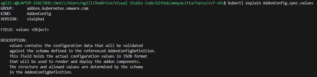
If deploying Kubernetes release 1.35 or later, this is done by way of three CRDs, which are detailed here. The AddonConfig and VSphereCPIConfig objects must be in place before the Cluster object. There are examples on my GitHub here which will show the various objects needed in detail.
- Configure an AddonConfig object
- Configure a VSphereCPIConfig object
- Add a bootstrapAddons variable to the Cluster object.
Whichever way you do it, ultimately you are manipulating Antrea featureGates, which control the base configuration. These are well documented on Antrea’s website. However, bear in mind that, as Broadcom re-packages Antrea in Carvel, versions will be slightly lagged from the upstream source. Additionally, the Carvel package schema, which Broadcom create, may not include all features.
By way of example, BGP peering policy is possible in Antrea v2.3.0. However, the AntreaConfig custom resource definition (CDR) within API Group cni.tanzu.vmware.com (as in vSphere 8.0 U3e) does not contain the required schema to enable the feature flag. This means that although the BGP Policy CRD will exist in the VKS cluster, it will be ignored.
If an attempt is made to manually edit the config map for Antrea directly, this throws a reconciliation error for the kapp controller inside VKS and will place the VKS cluster into an unsupported state. In order to use BGP peering, we must wait for or request that Broadcom enable the BGP feature flag. Therefore, for Tanzu, BGP peering is only possible with Calico CNI. Broadcom automatically orchestrates static routes in the NSX SDN, which is their preferred design and is the reason they probably block BGP usage.

For Kubernetes release 1.35 and above, Antrea is controlled by the following spec. Which, as of VCF 9.0.2, appears to be restricted to encapsulation and SNAT flags only. BGP again looks only possible with Calico. There may be further YAML spec possibilities, but nothing is listed in the documentation.
Calico Networking Container Interface
Calico CNI will be deployed with a default iBGP mesh between all nodes, with IP in IP encapsulation and egress SNAT. In order to utilise routable pods, IP in IP must be disabled, and a global BGP peer must be configured to your layer 3 routers/switches. Outbound SNAT should also be disabled. It should also be possible to do this with Classic NSX using external IP’s on T0, though I haven’t yet tried.
The default iBGP mesh is used for pod-to-pod communication and scales up to 100 nodes per VKS cluster. To scale to the VKS maximum of 150, it’s recommended to enable route reflector clients on the TOR L3 devices and disable Calico iBGP meshing.
Route reflectors will distribute routes to all nodes unmodified, creating a full mesh without the need for every node to peer with each other; Only BGP peering to the route reflectors is needed. Below is an example of a Calico full iBGP mesh with eBGP peering to TOR L3 devices.

When configured, your network will know how to route directly to each allocated pod CIDR via the VKS node address. As the routing topology is present on your centralised L3 device, routing to/from pods is then possible from anywhere in the network, and egress traffic will flow directly from the pod address as SNAT is disabled.
This configuration has distinct advantages, such as higher performance (no encapsulation), the ability to observe pod traffic by IP within your network (no NAT) and the ability to disable static route creation in your load balancing solution.
When I come to deploy Tanzu in the lab, I will highlight exactly how to deploy each CNI. I’ll share example YAML files on my GitHub repo for easy replication and understanding.
Egress
Egress in Kubernetes relates to what happens to packets as they leave the cluster. The default for Tanzu depends on the CNI selected. Without routable pods, when traffic leaves the node, source NAT (SNAT) will be applied. This translates the header of the IP packet, so the source IP appears to be the IP of the Kubernetes node itself. When the destination responds, traffic will naturally flow back to the same node that it left from, ultimately keeping routing symmetric and traffic flow happy.
When routed pods are in use, i.e. you have NSX and Antrea, or you have Calico and are advertising the podCIDR to the underlay, you will be able to disable SNAT entirely. This means the IP header remains untouched, the destination will see the originating IP source header as the pod IP address – given this is routable, packets will return to the correct node automatically.
If you happen to disable SNAT without routed pods, then the destination system of the packet will send it to its default gateway, which will then send it to its default gateway and so on. Ultimately, the packet will get lost and will not return to the pod. If you were doing, for example, an HTTP connection, you would get constant SYN packets at the source and no SYN-ACK or, in other words, an acknowledgement from the destination.
In addition to SNAT, Antrea also has egress CDR’s which can be used to control:
- What IP the pod uses when leaving, either by IP or by a Pool of addresses.
- Bandwidth traffic shaping.
For Calico, you can perform the following egress options.
- What IP the pod uses when leaving either by IP or by a pool of addresses
- Configure egress gateways to control traffic flow.
Both Antrea and Calico will also permit the use of NetworkPolicy to constrain what connections are possible. This, however, is a subject for the NetworkPolicy section of this article.
Services
Services for the Supervisor and VKS clusters are provided by the load balancer associated with the Supervisor cluster. This is because Kubernetes, by default, will use the associated infrastructure provider to issue addressing. For the VCF9 supervisor, the only supported load balancers are:
- NSX Integrated Load Balancer
- Foundation Load Balancer
- AVI Load Balancer
- HA Proxy
Once the supervisor is up, services of type LoadBalancer will always obtain an IP address from the configured load balancer.
Also supported is the ability to run your own load balancer configured within the VKS cluster. There are a number of options for this, some of which I have experience with and recommend are:
- F5 NGINX Ingress Controller
- F5 NGINX Gateway Fabric
- F5 BIG-IP Container Ingress Services
- Citrix NetScaler API Gateway for Kubernetes
- Citrix NetScaler Ingress Controller
- HA Proxy Ingress Controller
Note that Ingress has been around for a long time and is slowly being replaced by Gateway API, for greenfield deployments, where possible, it should be configured as the default. Gateway API is a modern, extensible, role-oriented mechanism. Separating out responsibilities for platform, cluster and application components. For example, a platform engineer can deploy the Gateway and Gateway classes whilst the developer handles the HTTPRoute, service and pods.
With Gateway API, ReferenceGrants can be used to enable cross-namespace resources. For example, a shared certificate namespace can be created with TLS secrets, which a centralised Gateway can access along with the associated application in another namespace.
The different ingress or GatewayAPI implementations ultimately have to steer traffic to the pods. Below are five principal ways to do this within Kubernetes.
| Network Option | OSI Layer | Comments |
| ClusterIP | L7 | This is possible with certain load balancer implementations; the load balancing virtual server address is allocated from a routable address pool on the load balancer. Meaning it can be reached and used. The members of the load balancing virtual server become podCIDR addresses, from the associated ReplicaSet if managed by a Deployment. Under normal circumstances, podCIDR is not routable. However, as mentioned prior, it can be advertised using a routing protocol or routed to using automated static routing via the node IP. |
| NodePortLocal | L7 | This is a specific use case for AVI load balancer and Antrea CNI where only the nodes which are hosting pods for the given application are included in the load-balanced pool. |
| NodePort | L7 | Uses a high port range for NAT 30000-32767 by default. Each node will proxy an assigned port to every node into the service. Kube-Proxy on each node is responsible for creating the required iptables NAT entries. |
| LoadBalancer | L4 | This will look to the underlying platform infrastructure to allocate an IP address. |
For NodePort, as the NAT goes to all nodes, technically, the client’s traffic could end up on a node which is not hosting the pod. If this happens, an additional connection is made over the cluster network to the node which hosts the pod.

For NodePortLocal, the client’s traffic will always go to the node which hosts the pod, which in the below example is node2.

For LoadBalancer, client traffic will hit a directly routable address (assigned by the external load balancer) and then be redirected to whatever nodes are hosting the pods for the application. The service is associated with pods by leveraging an EndPointSlice, which tracks IP addresses of the backend pod endpoints.

Authentication
Authentication for Kubernetes is based on RBAC authorisation, and there are deep, granular permission capabilities within Kubernetes. From a Tanzu Supervisor perspective, you set permissions against the supervisor namespaces, which flow down for vSphere pods and the creation of VKS clusters.
Kubernetes RBAC works by linking the following objects.
| Object | Description |
| Role or Cluster Role | A role or cluster role contains permission rules that are additive. In Kubernetes, there are no “deny” rules. You use roles for specific namespaces, and cluster roles for cluster-wide permissions that apply to all namespaces. |
| Role Binding or Cluster Role Binding | A role binding or cluster role binding grants the permissions defined in a role or cluster role to a user or set of users. It holds a list of subjects (users, groups, or service accounts), and a reference to the role being granted. A RoleBinding is for specific namespaces. A ClusterRoleBinding is for cluster-wide access. |
In Tanzu VCF9, there is a new vCenter role in addition to permissions set directly on the namespaces. As with prior versions, adding yourself to the default administrators role for vCenter will grant you all abilities in Tanzu. The official document is here.
| Role | Description |
| Administrator Role | Grants all abilities, including the right asspciated with the supervisor administrator role |
| Supervisor Administrator | A Supervisor Administrator role can only be assigned on the Supervisor folder. You will be able to view the namespaces inventory only after assigning it the Read-only role on the Cluster. When the Supervisor Administrator role is assigned on the Supervisor folder, a context is created that gives access only to cluster level resources in the Supervisor and not the vSphere Namespace. That is, you cannot list or view vSphere Namespaces. To be able to view vSphere Namespaces when you log in through VCF CLI, you must have additional permissions on the specific vSphere Namespace. |
When you complete the identity broker configuration in VCF and link vCenter to, for example, LDAP or EntraAD, permissions from these identity providers will be available to configure against supervisor namespaces.
Unfortunately, there is no capability to add cluster roles. All permissions are set against individual namespaces, which then additionally flow into any provisioned VKS clusters.
That said, if you add a user to the SSO group Administrators@vsphere.local, the user or group will be granted vSphere administrator rights, which also grants additional rights within the supervisor to view all namespaces via a cluster role. The cluster role is constrained but has more permissions than a vanilla namespace owner.
For each namespace, the following roles are configurable.
| Role | Description |
| Namespace View | Read-only access for the user or group. The user or group can login to the Supervisor control plane and list the workloads running in the vSphere Namespace. This is the minimum permission to be able to login. |
| Namespace Edit | The user or group can create, read, update, and delete vSphere Pods, VKS clusters, and VMs. Users who are part of the Administrators group have edit permissions on all namespaces in the Supervisor. |
| Namespace Owner | Users or groups with owner can, deploy and administer workloads in the vSphere Namespace, Share the vSphere Namespace with other users or groups and create and delete additional vSphere Namespaces using kubectl. When users with owner permission share the namespace, they can assign view, edit, or owner permissions to other users or groups. |
When it comes to VKS clusters, the default bindings are quite limited. You will probably want to add your own RBAC roles and bindings. Identity provider users and groups are automatically passed down as subjects; you can then easily attach specific permissions to the custom roles or cluster roles as required.
It’s generally recommended to restrict edit and owner rights as they are overly exposed permissions. For example, there is no ability with an edit role to restrict access to particular namespaces within VKS clusters. The recommended route is to adhere to the principle of least privilege and only permit view rights, then add custom role bindings within the VKS cluster, specific to the needs of the given team/developer.
Certain roles within the business will require full access. Where possible, only managers or senior members of the team should be granted edit access. The example below shows how to create role bindings against SSO groups. In this example, the AD group tanzu-developer-app01-team-owner has been granted all API groups, resources and verbs for the app01 namespace. This can be combined with a vSphere SSO “view” role to grant specific namespace permissions within VKS clusters themselves.

Where required permissions are unknown, the audit logs will show which API calls were rejected for the given user. Using audit2rbac tooling, you can quickly and efficiently identify and create missing RBAC roles.
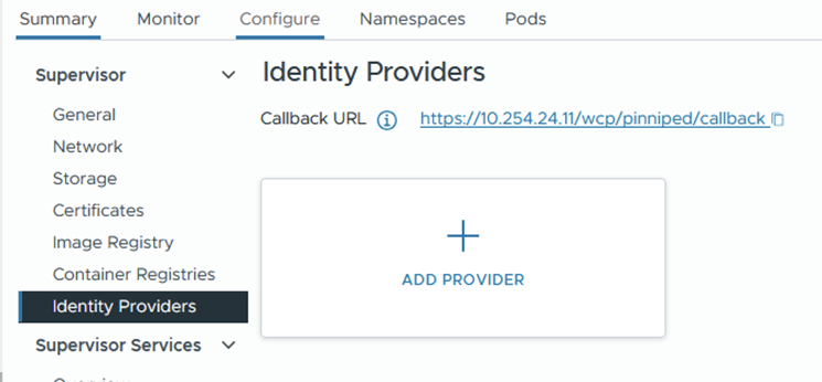
Another route for authentication into VKS is to configure OIDC authentication. This is achieved by attaching a provider configuration to the supervisor. The mechanism uses Pinniped, which is a VMware open source identity project for Kubernetes. Because this uses OIDC, the logins are subject to additional security measures. For example, with EntraAD conditional access policies.
For example, the order of configuration for EntraAD is as follows:
- Configure an app registration from the Entra AD portal.
- For added security, set the supported account type to this organisation only.
- Paste in the callback URL found from the supervisor > identity provider page.
- From certificates and secrets, generate a new secret and note the value and ID pair.
- Complete the add provider wizard from vSphere, entering the details captured from the app registration. Below is an example only.


- Install Tanzu CLI and initialise
tanzu init- Install the TKG plugin
tanzu plugin install --group vmware-tkg/default- List the VKS clusters
Tanzu cluster list -A- Generate a baseline kubeconfig file. This is distributed to the developers who reference it for logging in using kubectl. Save the unused kubeconfig file and distribute it.
tanzu cluster kubeconfig get vks-cluster-example --namespace=vks-namespace-example --export-file=~/.kube/oidc-entra-vks-cluster-example- From a developer’s machine, reference the kubeconfig file when logging in. Although you can reference it directly using “–kubeconfig” from the kubectl command line. You can also use the environmental variable $KUBECONFIG.
export KUBECONFIG=~/.kube/oidc-entra-vks-cluster-example
kubectl cluster-info
DNS
Most Kubernetes distributions run CoreDNS, which acts as an internal cluster DNS resolver. Nodes, pods, etc. will use CoreDNS as their resolver, which will have an additional forwarder back to your environment’s external DNS servers (Active Directory, for example). This means resolution of K8 occurs naturally using internal cluster resolution, and external systems (VM’s, Physical systems, etc.) will also be resolved, all using the same DNS service.
When you deploy Tanzu and select DNS servers, it’s these that get added to the “.” forwarder inside CoreDNS. You can check and modify the configuration by modifying the ConfigMap inside the kube-system namespace. For most environments, the defaults are good enough.
kubectl get cm -n kube-system corednsIn the example below, cluster.local will resolve using CoreDNS and anything else will use the forwarder of 10.166.101.254 by way of the “forward .” entry.

Most K8 clusters, by default, will be “cluster.local”, which is normal for most Kubernetes environments. You can change this for VKS clusters, but it’s not possible for the supervisor. Broadcom and the IT industry generally do not want “.local” domains being used any more as they tend to cause issues with resolution. However, for Kubernetes, it remains present and active in almost all deployments I have seen. As the DNS name is internal only, I personally would leave it as-is, rather than set up a unique DNS structure per cluster.
For applications being built, the recommendation is to automatically plumb these into the network. Arguably, the simplest way to do this is to use either GSLB with, for example, AVI, F5 or NetScaler. Alternatively, you can use ExternalDNS.
External DNS acts as middleware between annotations on the Kubernetes objects, such as Ingress or HTTPRoute and an external DNS zone. In order for this to work, your DNS zone must be on a supported provider list. There are many out of the box, and all the major players are on the list. You can even craft Kerberos tickets and have them update Microsoft DNS zones securely. Once configured, your applications will be automatically resolvable from outside of Kubernetes, which automates client connectivity and makes life much easier.
If security is a top priority, it’s possible to integrate ExternalDNS into private DNS zones on, for example, Azure, and have these connect over an internal secure link, i.e. Express Route or VPN.
Certificates
CA Trust
In order to modify the default CA certificate trust in the Supervisor cluster, edit the following config map.
kubectl edit configmap -n kube-system image-fetcher-ca-bundleOnce VIM is open, press I to change to insert mode, then paste the new PEM CA public key under the existing default Kubernetes cert. If you’re struggling with indentation, you could copy out and back in with the correct spacing using an external editor, or replace tab spacing with spaces by using “:set expandtab”. Once this config map is updated, the supervisor cluster will trust all certificates issued by this CA.

For VKS clusters, you can add CA certificates to the cluster object so they’re included when deployed. Please see this official article on how to review one of my VKS YAML files in GitHub.
Application Certificates
When it comes to containerised applications, the easiest way I’ve found to manage certificates is to use Certificate Manager. There are a bunch of in-tree issuers which you can use to interact with all the major CA providers, to automatically issue certificates and attach them to objects in the cluster. The full list is here. For now, I will show two simple options. At some point I will write another article specific to this subject. Outlining ACME and DNS-01 challenge authorisation which is a common pattern.
Option 1 – New PKI Hierarchy
With this option, we will create a new CA root file, which will also become the issuing CA. The configuration is very basic and straightforward. Modify the values for your needs.
## prepare an openssl config file
## you can also look in /etc/ssl/openssl.cnf
## if the options are already default then don't bother with this step
cat > openssl.cnf <<EOF
[ v3_ca ]
basicConstraints = critical,CA:TRUE
subjectKeyIdentifier = hash
authorityKeyIdentifier = keyid:always,issuer:always
EOF

## create a new root
openssl req -new -x509 -newkey rsa:4096 -nodes -keyout ca_private_key.pem -out ca_public_key.crt -sha256 -days 36500 -extensions v3_ca -subj '/CN=K8-RootCA/C=UK/ST=Home/L=Home/O=ACLAB.UK' -config openssl.cnf
Once done, you will have a root certificate which you can issue from. Next, we attach it to Cert Manager. First, log in to your Kubernetes cluster, then execute the following. These commands assume you already have Helm installed. If not, follow this article.
helm repo add jetstack https://charts.jetstack.io --force-update
helm search repo cert-manager
helm upgrade --install cert-manager jetstack/cert-manager --namespace cert-manager --create-namespace --version v1.19.4 --set crds.enabled=true --debug
Check that the pods are all running
kubectl get pods -n cert-managerCreate flat base64 encoded files for the public and private keys created earlier.
cat ca_public_key.crt | base64 -w0 > ca_public_key_base64.pem
cat ca_private_key.pem | base64 -w0 > ca_private_key_base64.pem
Create a secret and cluster issuer. As this is a cluster issuer, it will be able to issue certificates cluster-wide.
apiVersion: v1
kind: Secret
metadata:
  name: aclab-tanzu-root-ca
  namespace: cert-manager
data:
  tls.crt: <paste in the contents of ca_public_key_base64.pem>
  tls.key: <paste in the contents of ca_private_key_base64.pem>
---
apiVersion: cert-manager.io/v1
kind: ClusterIssuer
metadata:
  name: aclab-ca-issuer
  namespace: cert-manager
spec:
  ca:
    secretName: aclab-tanzu-root-ca
Create a certificate to test.
apiVersion: cert-manager.io/v1
kind: Certificate
metadata:
  name: test-cert
  namespace: default
spec:
  commonName: test-cert.aclab.uk
  dnsNames:
    - test-cert.aclab.uk
  secretName: test-cert-tls-secret
  issuerRef:
    name: aclab-ca-issuer
    kind: ClusterIssuer
Confirm you have a secret and the certificate was issued.
kubectl get secret,certificate -n defaultOption 2 – Subordinate PKI Hierarchy
With this option, we will create a new subordinate issuing CSR, which you can have issued from an existing hierarchy. Normally, you would have this be issued from an offline root. Like the one in my PKI series article. The root certificate will have CRL revocation ability from the root CA which issued it.
openssl req -newkey 4096 -extensions v3_ca -nodes -addext 1.3.6.1.4.1.311.20.2=ASN1:PRINTABLESTRING:SubCA -subj '/CN=K8-SubCA/C=UK/ST=Home/L=Home/O=ACLAB.UK' -keyout ca_private_key.pem -out ca_public_key.reqOnce done, give the ca_public_key.req file to your PKI guy. He can issue this, publish it to your environment, for example, using dspublish if Active Directory. He will return to you a public key, which you’ll need to complete the public, private key pair. I’m assuming here the public key returned and was renamed as “ca_public_key.crt”.
Deploy Cert Manager.
helm repo add jetstack https://charts.jetstack.io --force-update
helm search repo cert-manager
helm upgrade --install cert-manager jetstack/cert-manager --namespace cert-manager --create-namespace --version v1.19.4 --set crds.enabled=true --debug
Check that the pods are all running
kubectl get pods -n cert-managerCreate flat base64 encoded files for the public and private keys created earlier.
cat ca_public_key.crt | base64 -w0 > ca_public_key_base64.pem
cat ca_private_key.pem | base64 -w0 > ca_private_key_base64.pem
Create a secret and cluster issuer. As this is a cluster issuer, it will be able to issue certificates cluster-wide.
apiVersion: v1
kind: Secret
metadata:
  name: aclab-tanzu-sub-ca
  namespace: cert-manager
data:
  tls.crt: <paste in the contents of ca_public_key_base64.pem>
  tls.key: <paste in the contents of ca_private_key_base64.pem>
---
apiVersion: cert-manager.io/v1
kind: ClusterIssuer
metadata:
  name: aclab-subca-issuer
  namespace: cert-manager
spec:
  ca:
    secretName: aclab-tanzu-sub-ca
Create a certificate to test.
apiVersion: cert-manager.io/v1
kind: Certificate
metadata:
  name: test-cert
  namespace: default
spec:
  commonName: test-cert.aclab.uk
  dnsNames:
    - test-cert.aclab.uk
  secretName: test-cert-tls-secret
  issuerRef:
    name: aclab-subca-issuer
    kind: ClusterIssuer
Confirm you have a secret and the certificate was issued.
kubectl get secret,certificate -n defaultSecrets
A Secret is an object that contains sensitive data, such as a password, a token, or a key. Such information might otherwise be put in a Pod specification or in a container image. Using a Secret means that you don’t need to include confidential data in your application code.
For the Supervisor and VKS clusters, secrets are encrypted via a local decryption key file, which is provided at boot by vCenter. The decryption key is stored in memory (tempfs) on the control plane cluster nodes and on disk in encrypted form within vCenter database.
The key is available in clear text to the root users of each system. Secrets held within the database of each workload cluster are stored in clear text. All etcd connections are authenticated with certificates that are generated at installation and rotated during upgrades. Manual rotation or updating of the certificates is currently not possible.
There is no other management within Tanzu for secrets. Some organisations require an externalised secret store, which has the ability to sync secrets into Kubernetes. There are many options in this regard. Here are two worth exploring.
Azure Key Vault Provider for Secrets Store CSI Driver allows you to get secret contents stored in an Azure Key Vault instance and use the Secrets Store CSI driver interface to mount them into Kubernetes pods. This is usually deployed along with Azure AKS. However, it can also be deployed on user-managed clusters. The following features are available:
- Mounts secrets/keys/certs to a pod using a CSI Inline volume
- Supports mounting multiple secret store objects as a single volume
- Supports multiple secrets stores as providers. Multiple providers can run in the same cluster simultaneously.
- Supports pod portability with the SecretProviderClass CRD
- Supports Linux and Windows containers
- Supports sync with Kubernetes Secrets
- Supports auto-rotation of secrets
HashiCorp Vault has an extensive use case and feature-rich product set.
Container Registry
The preferred container registry for Tanzu is Harbor. This can be deployed as a service inside the supervisor cluster; you could deploy an instance on each VKS cluster or on a shared infra VKS cluster.
Most of the supervisor services are wrapped into Carvel packages by Broadcom. I’ve found a number of issues with them over the years, either missing schema entries, out-of-date settings or just broken deployments when following the documentation. Commercial tickets to Broadcom do not provide quick answers. To be honest, I’ve lost hope. I’ve not done extensive testing with VCF9, so I hope things have improved. If so, I will edit this page and paste in the good news!
I love the concept of the supervisor as a top-tier management cluster. Deploying Harbor here makes a lot of sense. However, if you want full control, to use upstream code, much easier remediation and a much larger community for support. I recommend deploying a shared platform VKS cluster, on which you can install common, shared components like Harbor.
I’ll put something together in a deployment article later. For now, head over here and follow the instructions to deploy it. You can easily integrate with LDAP and use Trivy for container CVE scanning; it’s not hugely complicated and can be picked up easily.
Storage
Out of the box, VCF will allow you to attach persistent storage for pods against VMDK files in vSAN, Block or File datastores. The setup is automatic and painless. The only contentious issue is the read access mode. Kubernetes has four basic modes.
| ReadWriteOnce | Volumes can be mounted as read-write by a single node. ReadWriteOnce access mode can still allow multiple pods to access (read from or write to) that volume when the pods are running on the same node. |
| ReadOnlyMany | Volumes can be mounted as read-only by many nodes. |
| ReadWriteMany | Volumes can be mounted as read-write by many nodes. |
| ReadWriteOncePod | Volumes can be mounted as read-write by a single Pod. Use ReadWriteOncePod access mode if you want to ensure that only one pod across the whole cluster can read that PVC or write to it. |
In order to use a deployment with multiple pods and shared storage, you would need to have ReadWriteMany. Unfortunately, this is not possible with VMDK files via the default storage provider. Out of the box on VCF, you select a storage policy, which would be the default one used for vSAN (assuming you’re not using Block or NFS).

Which gets translated into storage classes.

If a PVC is created which binds to the storage class, the following occurs.


The VMDK file for this is then “floating” in the fcd folder in vSAN.

This can also be seen from the vSphere UI under the namespace. As you can see, the access mode is ReadWriteOnce.

It’s possible with vSAN to enable File Volume Support. This allows for file-based CIFS/NFS protocols, which can then be used to mount ReadWriteMany PVC’s in Tanzu. The configuration is outside the scope of this article. However, I will cover it in a layer deployment guide.
Additionally, many customers also have their own arrays. There are many vendor container storage interface (CSI) drivers available. I’m most familiar with NetApp Trident, which has feature-rich integration with multi-protocol NetApp arrays. The sky is the limit, supporting anything from a vanilla NFS mount to a multi-site Metro Cluster. You can additionally combine Trident with Trident Protect, which provides protection for the metadata inside etcd. This is very similar to Velero and Veeam Kasten, which keep historical copies of the metadata, usually in some form of S3 bucket outside the cluster.
NetApp with Trident and Trident Protect will give you a full suite of protection with rich enterprise features. In many ways, it exceeds that of VMware Live Recovery with:
- Array or non-array replication of persistent volumes.
- Array replication of S3 buckets for metadata (backed up from etcd).
- Ability to perform restores using Snap Mirror and Flex Clone to:
- Same cluster, same namespaces.
- Same cluster, different namespaces.
- Another cluster, same namespaces.
- Another cluster, different namespaces.
- Restores can be done using hardware-integrated snapshots, flex clones and Snap Mirrors.
- Full orchestration through CI/CD pipelines.
I’ve personally used the tool to perform entire site disaster recovery easily within a 15-minute recovery time objective. This is on par with the best enterprise recovery software out there.
Network Policies
To stop unwanted lateral movement within the cluster, the recommendation is to configure NetworkPolicy objects, which is Micro-segmentation for Kubernetes. Traffic should be whitelisted as required, only allowing precise traffic flows based on what the application needs.
A simple implementation of this is shown below. This will permit all outbound traffic but reject all inbound traffic unless specifically whitelisted.
You would apply the same “default-deny-ingress” policy to all other application namespaces, so no traffic can flow in or out unless specifically whitelisted. This is easier than specifically denying outbound traffic. Although this can also be done if needed.
Care needs to be taken to also include traffic from outside of the cluster, for example, from load balancers. Once configured, the environment is deemed secure by default.
There are plenty of rich examples of NetworkPolicy within the official documentation.

Pod Security Standards
Configure pod security standards using standard labels against namespaces. These are important container security controls, for example, blocking privilege escalation and the ability to run applications as root. If you are able to root into a container, you can do some scary things.
I have a hacker friend who listed off a number of things you can do, including being able to get into the node itself. Once he started talking about what he could do with eBPF, I listened intently. Being able to decrypt TLS with no MITM technique is frankly frightening.
Thankfully, unlike other Kubernetes implementations (cough, Azure AKS, cough), the default mode is restricted, not privileged. Without needing to rewrite the entire list, please reference this article for a full list of the three security standard labels and what they bring or don’t bring to the game.
The important extracts from an example deployment, which is able to run in a restricted namespace, are below. The Docker image used is here.

Backup
The vanilla vCenter VAMI portal has a built-in ability to back up the supervisors and control plane configurations. The recommendation is to back up via, for example, SFTP and replicate the backup to a second location. Should a restore be needed, the supervisor will be restored along with vCenter.

For backups of VKS and also more granular elements of the Supervisor, Velero is your friend. This is a Broadcom-backed open source project which allows you to back up persistent data (volumes) and also metadata from etcd for your applications. You can also just include everything across the entire cluster.
Backups are stored centrally outside of the cluster, usually in a cloud or on-premises S3 bucket. You will want to ensure that the bucket is replicated in at least two locations. Once configured and backed up, the great thing about Velero is that the backups themselves are the source of truth. If you lost your cluster, after a new one is instantiated, you can simply re-connect Velero to the S3 bucket and perform a restore. There is no indexing or any other hard dependency that lives inside the cluster.
Below is a vanilla test setup to show how it works, for production do not run S3 over HTTP.
## create a credential file
CRED_PATH=velero-s3-target-credentials
cat << EOF > $CRED_PATH
[default]
aws_access_key_id=<enter id here>
aws_secret_access_key=<enter secret here>
EOF

## setup velero
NAMESPACE="test"
BUCKET="velero-backups"
REGION=minio
S3URL="http://minio.aclab.uk"
PublicURL="http://minio.aclab.uk"

## install velero
velero install \
--use-node-agent \
--features=EnableCSI \
--default-snapshot-move-data \
--provider aws \
--secret-file $CRED_PATH \
--bucket $BUCKET \
--backup-location-config region=$REGION,s3ForcePathStyle="true",s3Url=$S3URL,publicUrl=$PublicURL \
--plugins velero/velero-plugin-for-aws:v1.12.0 \
--wait

## validate pods are started and healthy
## node agent is deployed as a deamonset so one will exist per worker node
kubectl get pods -n test
kubectl logs deployment/velero -n test

## backup a namespace and include snapshots of persistent volumes
velero backup create test --include-namespaces=test --exclude-cluster-scoped-resources=true --snapshot-volumes

## validate
velero backup get
velero backup describe test --details
velero backup logs test

## if restoring in a disaster senario, first
## setup the new cluster
## re-attach the same backupstoragelocation then set as read-only
## set backup to read-only to protect it before restoring
kubectl patch backupstoragelocation default --namespace velero --type merge --patch '{"spec":{"accessMode":"ReadOnly"}}'
## perform the restore
velero restore create --from-backup test --restore-volumes=true --include-resources deployments,pods,persistentvolumeclaims,persistentvolumes
## if you want to re-use the backuplocation set it back to write
kubectl patch backupstoragelocation test --namespace velero --type merge --patch '{"spec":{"accessMode":"ReadWrite"}}'
o11y (Observability)
Any observability platform worth its salt must cover the four base pillars:
- Profiling – Identification of inefficiency that may be impacting application performance.
- Metrics – Health and performance metrics across platform and application stacks as a whole.
- Tracing – Collecting and analysing data about the requests that flow through the system as a whole.
- Logging – Logs from nodes, pods, auditing, and also from application runtimes such as dotnet and C#.
I’ve spent considerable time consulting with clients using Kube Prometheus Stack. This is a community-backed project that allows you to stand up a pretty decent observability baseline inside your cluster in minutes using Helm. It’s what Red Hat OpenShift bases its observability on, so it’s certainly a decent place to start.
Getting the o11y stack to monitor exactly what you need for your application, sorting logging, tracing, alerting, dashboards, etc., and getting developers’ buy-in, can take time. You will probably want to nominate someone to own its development. Observability is a big area and is critical to ensure that your platform runs well.
A deployment of Kube Prometheus Stack includes the following components. The deployment is best performed using Helm, which can be easily customised.
- HA Prometheus instance deployed with Prometheus operator for storing metrics.
- Pre-built Prometheus recording and alerting rules.
- Prometheus node exporter to grab OS metrics from the nodes themselves.
- Prometheus blackbox-exporter to scrape metrics from an endpoint address over HTTP/S, DNS, TCP, ICMP or gRPC.
- Prometheus adapter for Kubernetes Metrics API – acts as a translator between Kubernetes and Prometheus, enabling Horizontal Pod Autoscaler (HPA) to scale pods based on any metric Prometheus collects.
- Kube-State-Metrics to gather metrics from objects in Kubernetes.
- HA Prometheus Alert Manager to manage notifications based on Prometheus alerting rules.
- Grafana for dashboards and graphs of stored metrics.
- Prometheus and Alerts Manager are automatically added as data sources into Grafana.
- A collection of Grafana dashboards from the Kubernetes-mixin project.
In addition, you will also want to configure the following components to complete the stack.
- Agents/Collectors to process logs and tracing data. For example, Grafana Alloy or upstream OpenTelemetry.
- Grafana Loki for storing logs.
- Grafana Tempo for tracing.
- An S3 back end for Loki and Tempo to use for storage.
Daemonsets are usually used to collect pod logs from /var/log/pods/*/*. Within this path are stdout log streams from all pods. As long as the application logs output to stdout, the logs will probably be there. Open Telemetry can additionally enrich logs with, for example, k8sattributesprocessor.
Additional collectors may also be required within each namespace, for example, to collect application runtime-specific information, logs, traces, application metrics, etc. From a given SDK. For example, dotnet can export to OTLP for logging and tracing and Prometheus for metrics. Grafana will be able to correlate all three sources. The graphic below from Open Telemetry visualises it all hanging together.

You can deploy Loki and Tempo with Helm or as operators. The advantage of the operator is that all the configuration is done through Kubernetes CRDs. This is how Prometheus is configured as part of Kube Prometheus Stack. The potential disadvantage is that there is not always 100% feature parity with upstream releases, as the code is a little further downstream.
If you have the cash, I would also recommend externalised cloud tools. The best one I have seen is Datadog, their demo blew me away and is, in my view, friendlier than Grafana Cloud. Taking this road can help move things along faster. Both allow trials and demos, which are well worth exploring.
Conclusion
This concludes the article for Tanzu fundamentals. If you got this far, well done. Over time, I’ll create more articles for the actual deployment of the various elements mentioned.