
In this article, we will be exploring deploying Tanzu on VCF9 with NSX classic networking, also using NSX load balancer (not AVI).
Navigation
- Introduction
- Configure the supervisor Cluster
- Confirm Supervisor Deployment
- Set up Client Tools
- Deploy Supervisor Services
- Deploy vSphere Kubernetes Service
- Deploy Default Antrea with SNAT and Encapsulation
- Conclusion
Introduction
This follows on neatly from my VCF9 with NSX Classic Networking post; in a way, the post is a prerequisite for this article. We have NSX stood up with an Active/Active edge cluster, a Tier-0 router is configured and is exchanging prefixes with the external layer 3 device using BGP. An AVI load balancer has not been installed or integrated; this post doesn’t cover that. I’ll add a post for that in the future.
Configure the supervisor Cluster
First off, we have to configure the supervisor cluster. To do that, head over to vSphere and into supervisor management on the main menu.

Click the get started button, for this we will do a manual deployment. If automating, you can import a JSON file using the get started with config button. On my GitHub is a copy of the JSON file used for this deployment.

Select NSX Classic, click Next.

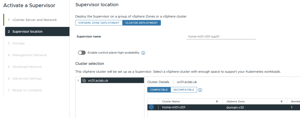
Select the cluster deployment and the cluster to deploy to. If you happen to have multiple zones, you can stretch the supervisor nodes across them by doing a zonal deployment. In the lab, I’m only deploying a single supervisor node, hence the control plane HA box is not enabled.
Select the default VCF storage policy. If this were a larger cluster, you could have different policies. It’s a good idea to ensure that the control plane storage is as resilient and protected as possible. For example, I’ve seen the other two storage areas fill up the volume and crash the supervisor nodes.
- Control Plane – this is for the supervisor virtual machines
- Emphemeral – transit storage for pods, for emptyDir volumes, config maps, for example.
- Container image – cache for vSphere pod container images

For management, you could place this inside an NSX segment. I’ve chosen to keep it on the same VLAN that is generally used for all other management components. I don’t have DHCP in that VLAN, so I have chosen static addressing. We need a total of 5 addresses, 3 for the nodes, 1 for upgrades and 1 more for the VIP.
Though, to be fair, in this lab we will run a single control plane node, so we only need 3 addresses.

The workload network page needs some explaining. First off, we select the VDS switch and edge cluster, DNS servers and Tier-0 gateway; this is all straightforward.
The NAT mode box is checked, which will deploy non-routed pods; the pod CIDR will be inside Kubernetes in the overlay. If we uncheck this box, then routed pods will be deployed. For the purposes of this lab, I will be deploying routed pods. They give better performance, as no encapsulation is needed between the Kubernetes nodes.
The subnet prefix is the default allocated CIDR size for each namespace deployed. It determines how many vSphere pods you can deploy; each one will consume a single address. I tend to prefer VKS cluster workloads, so I will leave this at a default /28.
The namespace network is an internal range from which pod addressing is allocated. Given we have unselected NAT mode, this will be fully routable and cannot overlap with IPs of Supervisor Management components (VC, NSX, ESXs, Management DNS, NTP) and should not overlap with other datacenter IPs communicating with pods. How big it needs to be really depends on how large your deployment is. Remember, every node will consume a /24, you can work it out from there.
If you need 800 pods, then you will need at least 4 nodes to accommodate all the addressing, and add another for reserve capacity. This assumes the nodes are large enough to accommodate the CPU and memory requirements. You will also have three control plane nodes. This takes is to a total of 8 x /24, which is at least a /21. Add another few clusters of this size, and you will need a /20 with some room spare for the /28 networks for any supervisor namespaces.
The service CIDR is an internal-only network and can remain the default unless it happens to overlap with IPs of Supervisor Management components (VC, NSX, ESXs, Management DNS, NTP). If you did overlap, then from a Kubernetes cluster perspective, communication to the management components would be inside the cluster and wouldn’t route out.
Ingress CIDRs are for an external CIDR block for Kubernetes Ingress objects and services of type LoadBalancer. These will be allocated by the NSX load balancer component and will be redistributed from NSX via BGP to the external network. The Supervisor control plane will allocate 1 x IP per namespace and 1 x IP for every service of type LoadBalancer. This will need to be sized accordingly. Usually, you do not consume so many services of this type; you can share one for each VKS cluster using an Ingress Controller or Gateway API object, hence /24 should be plenty.
Egress CIDRs are only applicable when you are not doing routed pods; these are used for SNAT rules, which will then be advertised out to the external network via BGP. This will need to be a routable network which doesn’t conflict.
Here is the configuration of my lab. Click next.

On advanced settings, enter an alternative SAN name for the default certificate and the supervisor control plane size. Small is the best starting point; don’t use tiny, as you’ll have no spare capacity. Remember, you can scale up but not down very easily later. Check the export button if you want to redo the wizard at a later date.

Review the details and then click finish.

Confirm Supervisor Deployment
At this point, a number of tasks will kick off, and the control plane node will automatically deploy from a new content library, which the wizard will create.


From supervisor management > supervisors, you can monitor progress in the GUI.

If you SSH to the vCenter server, you can run the command below to grab the root password for the supervisor. If you log in, you can run kubectl commands locally, which is super handy. You will also have a cluster-admin role binding. The IP address will only show when the first node and VIP are online.
/usr/lib/vmware-wcp/decryptK8Pwd.py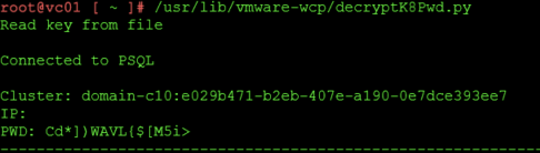
The Workload Control Plane (WCP) service on vCenter is responsible for the deployment of the supervisor, the configuration of NSX, etc. You can control the service and check the logs with the following commands.
## restart
service-control --restart wcp

## check status
service-control --status wcp

## check logs
tail -f /var/log/vmware/wcp/wcpsvc.log
On the ESX host, Spherelet will be deployed and configured, which will connect back to the supervisor node. You can check its status with the following commands.

## check service status
/etc/init.d/spherelet status

## check logs
tail -f /var/log/spherelet.log
If you log in to the supervisor node, the root user will already have the kubeconfig file populated in ~/.kube/config. This means you can run kubectl commands and check that things have started.

## check nodes are in a ready state
kubectl get nodes

## check pods are running
kubectl get pods -A -o wide
Once the pods are all good, check NSX, and you will find the load balancer configurations.

If you look at the topology of NSX, you can see how it builds it. A tier-1 gateway is deployed with a segment attached for the supervisor nodes. The tier-1 gateway is linked to our tier-0 gateway.

Set up Client Tools
From vSphere to go supervisor management > supervisors > click the supervisor. On the summary tab, it will show the Kubernetes API server address. This is allocated from the ingress CIDR we used when configuring the supervisor.

Connect to this over HTTPS, and you will be presented with a page where you can download the VCF CLI. This replaces kubectl vsphere as in prior versions. Download the flavour you need. In my case, I run Fedora in WSL.

Run the following to set up the VCF and Kubectl CLI and to connect to the Supervisor.
## extract and install cli tools
tar -xvzf vcf-cli.tar.gz
sudo mv vcf-cli-linux_amd64 /usr/local/bin/vcf
rm vcf-cli.tar.gz
curl -LO "https://dl.k8s.io/release/$(curl -L -s https://dl.k8s.io/release/stable.txt)/bin/linux/amd64/kubectl"
sudo mv kubectl /usr/local/bin/

## confirm cli install
vcf version
kubectl version

## sort auto complete and 'k' alias for kubectl
sudo dnf install bash-completion -y
vcf completion bash > $HOME/.config/vcf/completion.bash.inc
printf "\n# VCF shell completion\nsource '$HOME/.config/vcf/completion.bash.inc'\n" >> $HOME/.bashrc
kubectl completion bash | sudo tee /etc/bash_completion.d/kubectl > /dev/null
sudo chmod a+r /etc/bash_completion.d/kubectl
echo 'alias k=kubectl' >>~/.bashrc
echo 'complete -o default -F __start_kubectl k' >>~/.bashrc
source ~/.bashrc

## login to supervisor
vcf context create sup01 --endpoint sup01.aclab.uk --username administrator@vsphere.local --insecure-skip-tls-verify

## switch to the supervisor context
vcf context use sup01

## show nodes, you should see the supervisor node and the esxi worker node running spherelet
kubectl get nodes -o wide
Below, the node address for the supervisor is taken from the namespace CIDR; the ESX host is on its default management network, which in my lab is VLAN 100.

Deploy Supervisor Services
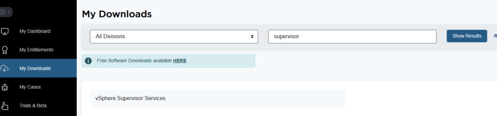
At this point, we want to upgrade the VKS supervisor service and also install the local consumption interface. To do this, we need to log in to the Broadcom portal. Click My Downloads, then search for supervisor. Click vSphere supervisor services.
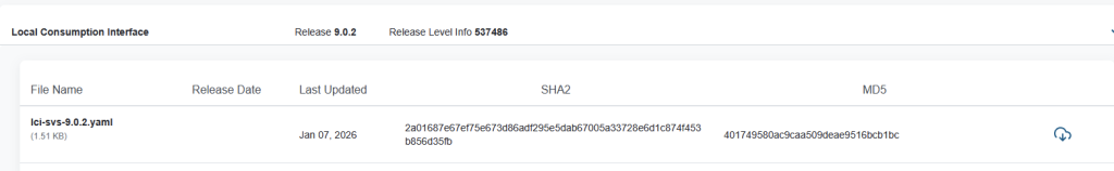
Download the YAML file for vSphere Kubernetes Service and Local Consumption Interface. I’m running 9.0.2, so I can download the latest. If you’re not sure, check the interop matrix and also the supervisor services GitHub page. Between those two, you can figure out compatibility.

Once you have the YAML files, from supervisor management > services > select actions on Kubernetes Service and add a new version.
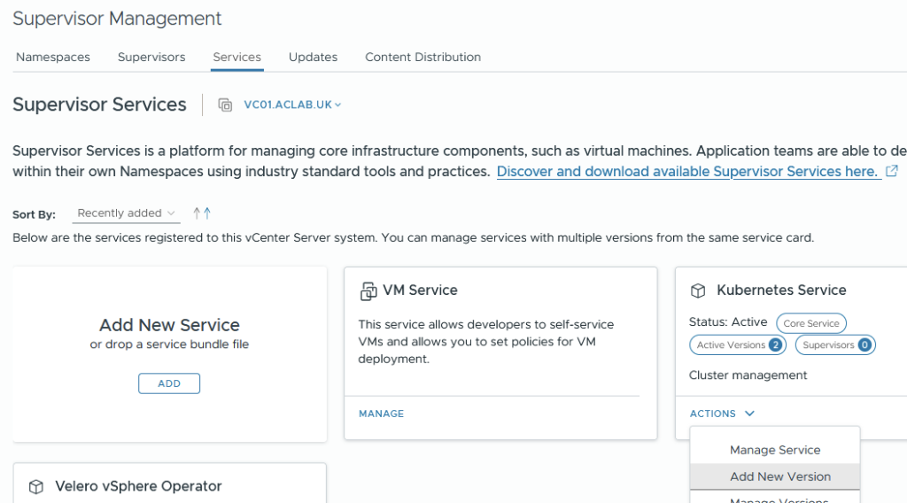
Upload the YAML file we downloaded, and click finish.


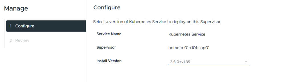
Next, go into supervisor management > supervisors > select the supervisor > configure > overview within supervisor services. Select the Kubernetes service, then click manage.

Select the newer version.
Ignore the warning about only having one supervisor node, and complete the wizard.

Wait for the reconciliation process to complete; it can take a few minutes.

You’ll need to wait until all of these pods are restarted with the new versions.
watch kubectl get pods,deploy,ds -n svc-tkg-domain-c10
Once complete, we will want to install the local consumption interface, which gives better Kubernetes visibility from vSphere. From supervisor management > services > click add new service.

Upload the consumption interface YAML file, and click finish.

From supervisor management > supervisors > select the supervisor > configure > overview > click available and then install the local consumption interface.

Complete the wizard, leaving everything as the default.

Wait for the reconciliation process to complete.

The resources tab on a namespace will now show more information.

Deploy vSphere Kubernetes Service
Next, we need to deploy VKS services, which are the guest-based Kubernetes clusters. The supervisor is the management cluster, and the VKS clusters are the workload clusters. They have their own control plane with a unique etcd and dedicated workers.
Deploy VKS Namespace
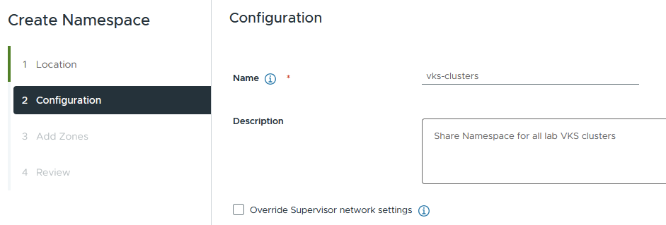
Next, we need to create a namespace as a home for the VKS clusters. You can create multiple of these and give granular permissions to each, or, for example, have a single shared one. In my lab, I just have a shared “vks-clusters” namespace, to which all VKS clusters reside.
From supervisor management > namespaces > click new namespace.

Select the supervisor

Enter a DNS-conformant name; you can override the networking here. This allows you to configure the following overrides for this particular namespace.

For our lab, we will leave it to the default and not override anything.
Select the zone for the namespace; we only have one. Click next.

Review the settings and click finish

This will create a brand new NSX segment.

Tier-1 gateway attached to the shared Tier-0 gateway.

NAT rules.

Load Balancer.

And the gateway firewall rule set.

Go to supervisor management > click the vks-clusters namespace. On the summary page, add storage and select the VCF storage policy.

From the VM service tile, click Add VM class. These are the allowed sizes for the VKS nodes. In my lab, we will be using best effort small.

Connect to VKS Cluster Namespace
Log in to the supervisor and connect to the vks-clusters namespace we just added. When you do a refresh, it may see that an existing token exists, in which case you won’t get one for vks-clusters.

You can either override the context for sup01, delete and re-create the contexts or modify the YAML files to include a default namespace. The choice is yours. Unfortunately, I couldn’t find the vcf auth token to remove it.
## change the namespace on the sup01 context
kubectl config set-context sup01 -n vks-clusters

## delete and recreate
vcf context delete sup01
vcf context create sup01 --endpoint sup01.aclab.uk --username administrator@vsphere.local --insecure-skip-tls-verify
vcf context use sup01:vks-clusters
Deploy VKS Cluster
Once logged into the vks-cluster namespace, create the VKS cluster. Download the YAML example from my GitHub, then run this command. As this is a lab, the example VKS cluster only has one control plane node and one worker.
kubectl apply -f vks-3.6.0-aclab-antrea-routed.yamlWithin a few seconds, the control plane node will be deployed. After this, the worker node will be deployed.

A second segment for the VKS nodes will be attached to the Tier-1 gateway for this namespace.
A layer 4 load-balancing virtual server will be added for the Kubernetes API inside the VKS control plane.

This is advertised to the external network via BGP. Below is an extract of the routing table on my MikroTik router.

Connect to VKS Cluster
Next, log in to the VKS cluster by creating the relevant context.
vcf context create aclab-vks-01 --endpoint sup01.aclab.uk --username administrator@vsphere.local --insecure-skip-tls-verify --workload-cluster-name aclab-vks-01 --workload-cluster-namespace vks-clusters
Once done, you will have a context for the supervisor namespace and another for the VKS cluster itself.

Switch to the VKS context and do a basic check.
## switch to vks context
vcf context switch aclab-vks-01:aclab-vks-01

## grab nodes
kubectl get nodes -o wide
We can also SSH directly to the VKS control plane node. To do this, run the commands below.
## switch to supervisor namespace
vcf context use sup01:vks-clusters

## grab the ssh password
kubectl get secrets aclab-vks-01-ssh-password -o jsonpath='{.data.ssh-passwordkey}' | base64 -d

## connect to the control plane node, grab the IP from vCenter
ssh vmware-system-user@10.167.0.50

## connect using ssh key instead
kubectl get secrets aclab-vks-01-ssh -o jsonpath='{.data.ssh-privatekey}' | base64 -d > sshkey
chmod 700 sshkey
ssh -i sshkey vmware-system-user@10.167.0.50
Validate Antrea Routed Pods
You can validate the pod networking CIDR by running the command below. This returns the CIDR for each node; the subnet shown aligns to the namespace network, which is correct. This is fully routable.
kubectl get nodes -o yaml | grep podCIDR:
The pod CIDR is directly available on the external network. This is achieved by the NSX Tier-1 gateway static routes being redistributed into BGP.


At this point, we can deploy a basic application, for example, a minimal nginx unprivileged deployment, which will work with a restricted pod security policy. Once deployed, grab a pod address.
## deploy application
kubectl apply -f nginx-unprivileged-minimal.yaml

## grab the pod address
kubectl get pods -n app01-dev -o wide
From my machine outside of NSX, I can connect directly to the pod that’s running. This shows that routable pods work. There is no encapsulation or source NAT required, as NSX, as the SDN is handling routing.

Note, the second pod, which is pending, is intentional; if you look at the YAML manifest, there is pod anti-affinity configured, which will only schedule the pod if on different nodes. Given that I only have one node, we only have one pod scheduled. If you run the below, you will see what is going on.
## note the pod is spawned from a deployment so the numbers at the end will be different in your environment
kubectl describe pod -n app01-dev nginx-example-01-55f4b6b897-pdpvm
Deploy Default Antrea with SNAT and Encapsulation
To show what happens with default non-routable pods, we will create a namespace and override the networking. From supervisor management > namespaces, add a new namespace.
Select the supervisor.

Give it a name and tick the override box.

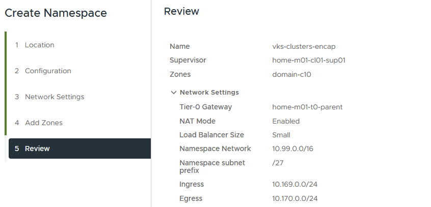
Select a Tier-0 gateway, enable NAT mode and load balancer size.
The namespace network no longer needs to be routable, but still cannot overlap with IPs of Supervisor Management components (VC, NSX, ESXs, Management DNS, NTP). How big it needs to be really depends on how large your deployment is. Remember, every node will consume a /24; you can work it out from there.
The namespace subnet prefix is the default allocated CIDR size for each namespace deployed. It determines how many vSphere pods you can deploy; each one will consume a single address. I tend to prefer VKS cluster workloads, so I will leave this at a default /28
Ingress CIDRs are for an external CIDR block for Kubernetes Ingress objects and services of type LoadBalancer. These will be allocated by the NSX load balancer component and will be redistributed from NSX via BGP to the external network. The Supervisor control plane will allocate 1 x IP per namespace and 1 x IP for every service of type LoadBalancer. This will need to be sized accordingly. Usually, you do not consume so many services of this type; you can share one for each VKS cluster using an Ingress Controller or Gateway API object, hence /24 should be plenty.
Egress CIDRs are used for SNAT rules, which will then be advertised out to the external network via BGP. This will need to be a routable network which doesn’t conflict with anything else.
This is what I have configured for the lab.

Select the zone.

Review and finish.
NSX will be configured with the usual Tier-1 gateway, a dedicated segment, gateway firewall rule, load balancer and NAT rules.


Go to supervisor management > namespaces > click the new namespace. On the summary page, add the storage class and VM class.


We can then run the following commands to connect and deploy the VKS cluster. The YAML file for this VKS cluster is on my GitHub here.
## refresh the sup01 context context
vcf context delete sup01
vcf context create sup01 --endpoint sup01.aclab.uk --username administrator@vsphere.local --insecure-skip-tls-verify

## connect to the new namespace for this vks cluster
vcf context use sup01:vks-clusters-encap

## deploy the vks cluster
kubectl apply -f vks-3.6.0-aclab-antrea-default.yaml

## connect to the vks cluster
vcf context create aclab-vks-02 --endpoint sup01.aclab.uk --username administrator@vsphere.local --insecure-skip-tls-verify --workload-cluster-name aclab-vks-02 --workload-cluster-namespace vks-clusters-encap

## switch to the context
vcf context use aclab-vks-02:aclab-vks-02

## get podCIDR addressing
kubectl get nodes -o yaml | grep podCIDR
Pod networking is now on an internal Kubernetes network.

At this point, we can deploy a basic application, for example, a minimal nginx unprivileged deployment, which will work with a restricted pod security policy. Once deployed, grab a pod address.
## deploy application
kubectl apply -f nginx-unprivileged-minimal.yaml

## grab the pod address
kubectl get pods -n app01-dev -o wide
From my machine outside of NSX, I cannot connect. To reach the application, we either need to be inside the vks-clusters VPC or plumb in external connectivity. To do that quickly, we can patch the service to be of type LoadBalancer, which will create L4 connectivity via the NSX load balancer. A better route would be to set up Gateway API or Ingress, which will also attach to a load balancer, but at Layer 7. I will say more on this in another article; for now, we can run the below to connect at L4 via NSX.
## expose the service using NSX load balancer
kubectl patch svc nginx-example-01-svc -n app01-dev -p '{"spec": {"type": "LoadBalancer"}}'

## confirm an external IP is allocated from NSX
kubectl get svc -n app01-dev
As you can see, an address has been assigned from the ingress CIDR we assigned when we overrode the namespace networking.

Hit this address via an external browser on HTTP 80, and it will connect.

You may have noticed that the pod port in the prior example is 8080, and now the service is 80. This is because the service object is on 80, which connects to the pod on 8080.

Note, the second pod, which is pending, is intentional; if you look at the YAML manifest, there is pod anti-affinity configured, which will only schedule the pod if on different nodes. Given that I only have one node, we only have one pod scheduled. If you describe the pending pod, you will see what is going on.
Conclusion
This ends the article on Tanzu with NSX classic networking. There is much more to write about. I’m in the process of writing a general design/familiarisation guide for Tanzu. I think I’ll then dive into individual topics such as AVI, Gateway API, Secret Management, Authentication, DNS, Certificates, Network Policies, etc. There are many things to talk about within a Kubernetes environment, I find it intellectually fascinating, so I am very happy to keep writing posts about it.