
In this article, we will be deploying VCF9 with NSX classic networking. This is the way it’s done for all non-VCF deployments, for example, in vSphere 8.0 U3. Broadcom is committed to VPC networking. I don’t know how much longer the classic route will exist; however its where I have the most exposure to date, so I thought it best to write an article on it for the latest 9.0.2 of VCF.
We will follow on from the NSX networking section of my VCF9 Home Lab Article. Once you are at the point of the basic SDDC being stood up, stop there and come back here to configure NSX using the Classic pathway.
Navigation
- Introduction
- Configure Edge VTEP Pool
- Review uplink profiles with teamings
- Review and create transport zones
- Configure VLAN segments for the edge node external interfaces
- Configure distributed port groups for edge VLAN uplinks
- Configure distributed port groups for edge Transport uplinks
- Deploy edge nodes and form an edge cluster
- Deploy Tier-0 gateway
- Add a test segment and confirm routing
- Link Failure Testing
- Conclusion
Introduction
We start with the initial configuration within NSX. We have a fresh SDDC from the VCF installer, but so many things are not configured out of the box. We have no edge configuration, no gateways or segments. NSX doesn’t do very much at this point; there is a link to vCenter, and the ESX transport nodes are configured.
Configure Edge VTEP Pool
For the lab, I will be separating out the edge VTEP VLAN from the host VTEP VLAN. This isnt a fixed requirement, but is needed when doing some form of stretched cluster, for example, a vSphere Metro Storage Cluster (vMSC), or vSAN stretched cluster. With these kinds of setups, you will want the edge nodes to move freely between the physical locations, whereas the physical ESX nodes are static. Placing the ESX transport nodes in their own VLAN (one per datacenter) and the edge node in a stretched VLAN allows for this. I’m following this principle in preparation for a second site in my lab.
From NSX manager to go networking > IP address pools > add IP address pool. Give it a name, enable check overlap and click save.

Edit the address pool we just created and click Set on Subnets. Then click add subnet > IP range.

Fill in all the details. In my lab, 105 is the edge VTEP VLAN. My DNS server is a MikroTik router, which is also the default gateway. Click add > apply > save.

A subnet will now show.

Review uplink profiles with teamings
From system > fabric > profiles > uplink profiles. There is a default profile created by the VCF installer. FYI, this is attached to the transport node profile already by the installer. In my lab, the profile is called vc01-home-m01-cl01-home-m01-cl01-vds01.

If you click the teamings link, you can see how the installer has configured it. The default will load balance on the source, with all the others having a failover order. Two with no standby uplinks and two more with standby uplinks.

Additionally, we will create a new uplink profile for our edge nodes. You can use the defaults, but I prefer specific namings that match the edge node network cards.
This is what an edge node looks like on the inside. The diagram is for a bare metal node, but it pretty closely maps to a virtual machine node. The difference being there is no eth1 management interface and no bonds.

We’re aiming for this configuration.
| Edge NIC | NSX Teaming Policy | Port Group |
| eth0 | n/a | dp-vm-mgmt-v101 |
| fp-eth0 and fp-eth1 | Load Balance Source | dp-vm-edge-transport-v105 |
| fp-eth2 | Failover Order | dp-edge-uplink-a |
| fp-eth3 | Failover Order | dp-edge-uplink-b |
From system > fabric > profiles > uplink profiles, click add uplink profile. Enter a name, description and the transport VLAN, which is 105 in my lab.

Click the set link next to teamings and add the following, click apply and then save. We now have an uplink profile that will use the second and third NIC for VTEP tunnels, and the fourth and fifth NIC for VLAN uplinks.

Review and create transport zones
From system > transport zones. Review what is created by default.
“vcf-overlay-tz” was added by the installer and is where the ESX transport nodes are currently attached.
Click add transport zone and create a new “vcf-vlan-tz” VLAN transport zone. We select the VLAN uplink teaming names from the edge uplink profile we reviewed earlier. Also, add the VLAN uplink VLAN IDs and a decent description.

Configure VLAN segments for the edge node external interfaces
Next, we need to add VLAN segments for the Edge external interfaces to attach to. From networking > segments > click add segment. We need one for each NSX edge uplink VLAN. In my lab, these are VLAN 106 for uplink-a and VLAN 107 for uplink-b.
Click add segment, enter a name, select the VCF VLAN transport zone, fp-eth2 as the uplink policy name and VLAN 106, which is our first edge uplink VLAN.


Click add segment again, enter a name, select the VCF VLAN transport zone, fp-eth3 as the uplink policy name and VLAN 107, which is our second edge uplink VLAN.


Configure distributed port groups for edge VLAN uplinks
From vSphere, add two distributed port groups in trunk mode. Go to networking > right-click the default VDS from the VCF installer and add a new port group.

Give it a name, click next.

Set the mode to VLAN trunking. You can filter this down to just VLANs 106-107. Click next and finish.

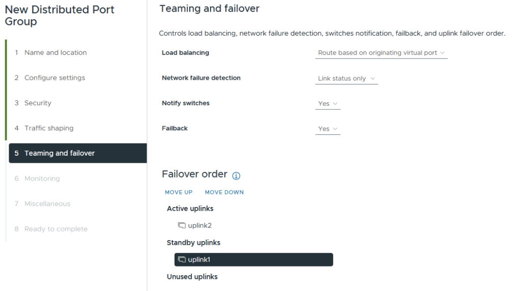
Edit the port group policies and configure uplink1 as active and uplink2 as standby.

Create another distributed port group for uplink-b.

Set VLAN trunking to 106-107, check the customise box, then click next until you get to teaming and failover.

Set uplink2 as active and uplink1 as standby. Click next until the end and finish.
You will now have two distributed port groups for the edge nodes to connect to for their VLAN uplinks to the outside world. In my lab, this is my MikroTik router.

Configure distributed port groups for edge Transport uplinks
Next, we will create a dedicated port group for the edge transport uplinks. We could reuse the VLAN uplinks, but we want an active/active failover policy for the transport links.
From vSphere, go to networking > right-click the default VDS from the VCF installer and add a new port group.
Enter an appropriate name. I include the VLAN tag to make it clear.

Set trunking mode and the VLAN to 105, click next and finish.

Deploy edge nodes and form an edge cluster
Next, we need to deploy the edge nodes; this is done from NSX Manager, which will push an OVF template into vSphere.
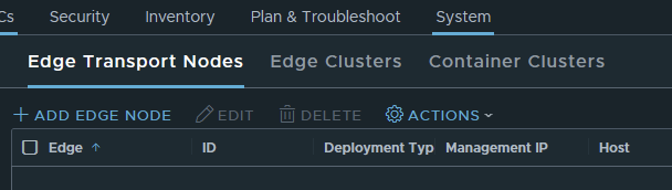
Go to system > nodes and click add edge node.
Enter the name, FQDN, select the form factor and configure the resource reservations. As this is a lab, I am not including a memory reservation. Additionally, I am only selecting medium. In production environments, do not remove the reservation. Click next.

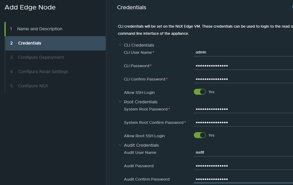
Enter the passwords as required, and click Next.
Select the compute resource and datastore. Click next.

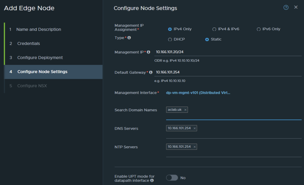
Configure the addressing, gateway, DNS, NTP, and if your hardware supports it, enable UPT mode. Click next.
We now have to configure the virtual switch to be placed inside the edge node itself.
For the name, you can use whatever you like; a simple option is nsxEdgeSwitch. The edge node will be attached to both overlay and VLAN transport zones. Select the uplink profile and IP pool previously created.
For the uplinks, note that the order is not linear. For some reason, fp-eth3 is above fp-eth2. In any case, this is what we want to configure. When done, click finish.
| Edge NIC | DPDK Interface | Use |
| fp-eth0 | do-edge-transport-v105 | VTEP Transport Network |
| fp-eth1 | do-edge-transport-v105 | VTEP Transport Network |
| fp-eth2 | dp-edge-uplink-a | Edge Uplink VLAN A |
| fp-eth3 | dp-edge-uplink-b | Edge Uplink VLAN B |

Repeat the above steps again, but enter details for edge node 02. From vCenter, you will see the OVF deployment.

From NSX, the deployment will show in progress.
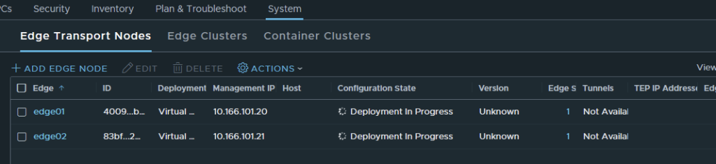
The edge nodes will automatically register themselves with NSX Manager; eventually, they will come back with success. We have multiple TEP addresses as we requested.

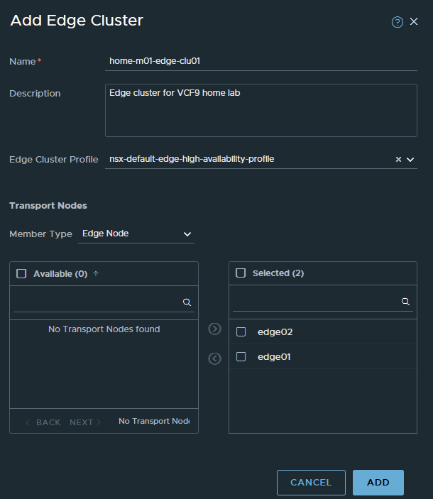
Next, we go to System > Nodes > Edge Clusters and create an edge cluster. To do this, click add edge cluster. We will use the name from the VCF planning workbook. Select the default HA profile, drop both nodes in and then click add.

Deploy Tier-0 gateway
Next, we need to deploy the Tier-0 gateway, which will interface with my external MikroTik router. For a production environment, it would be your layer 3 device, which is usually top-of-rack switches or firewalls.
Go to networking Tier-0 Gateways and click Add Gateway > Tier-0 Gateway.
For the name, we will use home-m01-t0-parent, which is what is in the lab planning workbook. The use of parent is useful when you plan to use VRF for tenant segmentation. A VRF is a unique layer 3 routing domain, which is a software instance of a Tier-0. Each VRF can peer with your external L3 device securely and independently, meaning you can have secure routing in/out for various workload types. For example, for PCI-DSS, you could have a CDE environment fully segmented off.
For the mode, I will select active/active. Select the edge cluster, enter a description and click save.

When asked about continuing to configure, say yes.

Configure Route Redistribution
Under route redistribution, click set.

Click add route redistribution, give it a name, then click set again.
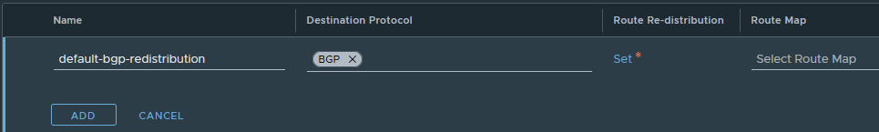
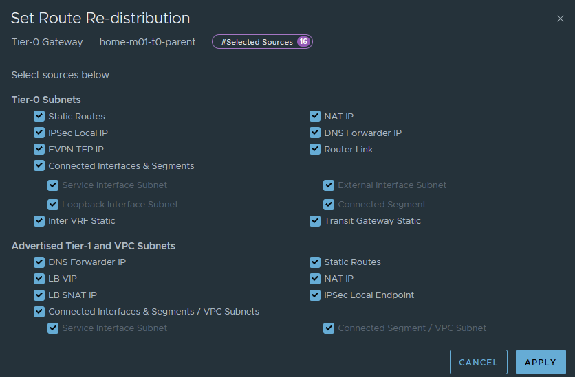
Tick all boxes for now. There are scenarios where you may want to add specific route-maps, in which case you will want a specific policy that only redistributes exactly what you want. In the lab, things are simple, and everything can be redistributed. This means the MikroTik router will have everything configured, advertised, segments, static routes, etc.
Click apply, add, apply, then finally save.
The redistribution policy has now been added.

Configure BGP
Under the BGP section, set the private AS number suitable for the environment. In my case, I am using 65500 in NSX and 64512 on my MikroTik.
The private AS number can be anything between 64512 and 65534. You will want an understanding of the wider BGP topology in your environment, having two AS numbers the same will technically mean iBGP, not eBGP. By default, AS Loop Prevention will stop prefixes in the RIB from being used actively in the routing table. You want two different AS numbers and to use eBGP from your NSX Edges to the exterior L3 routing device(s).
Click save to confirm the change.

Under the interfaces and GRE tunnel section, click set, next to external and service interfaces.

Click add interface and add the following, then click save.
We are labelling the uplink in parallel with the VLAN segment we added earlier, the IP address 10.166.106.1 for edge01.

Repeat for edge 02 uplink A.

Then edge 01 uplink B and edge 02 uplink B


Once complete, you will have 4 addresses for BGP to use with its neighbour relationships. Click close.

Under the BGP section, click set, next to BGP neighbours.

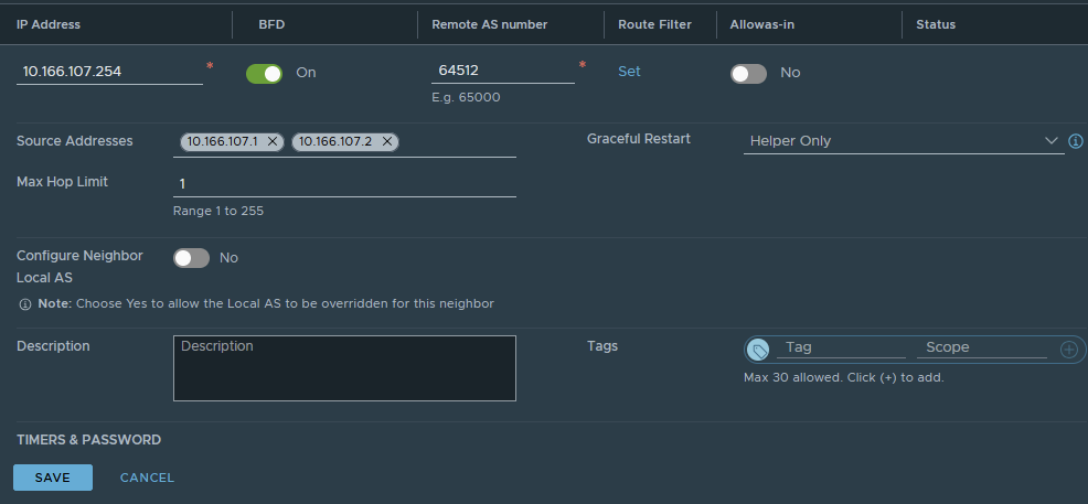
Click add BGP neighbour, enter the address of the external L3 device. In my lab, my MikroTik router is on 10.166.106.254 and 10.166.107.254.
Enable BFD, which provides faster failure detection times. This also has to be enabled on the L3 device, which is the case in my lab.
Enter the remote AS number; in my lab, this is 64512.
Add the source addresses of both edge nodes for this VLAN. If required, add a password. I don’t use one in the lab. Click save.

Repeat for uplink VLAN 107. Click save.
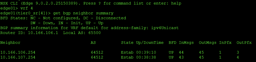
The neighbours will show success.

From the external routing device, we can also see active neighbours.

Add a test segment and confirm routing
Next, we will quickly add a segment to NSX and show its behaviour. From networking > segments, click add segment. Give it a name, directly attach it to Tier-0 and the overlay transport zone. For the subnet, we will give it 10.166.150.254/24, which will become the default gateway in the segment. Click save and say no to continue configuring.

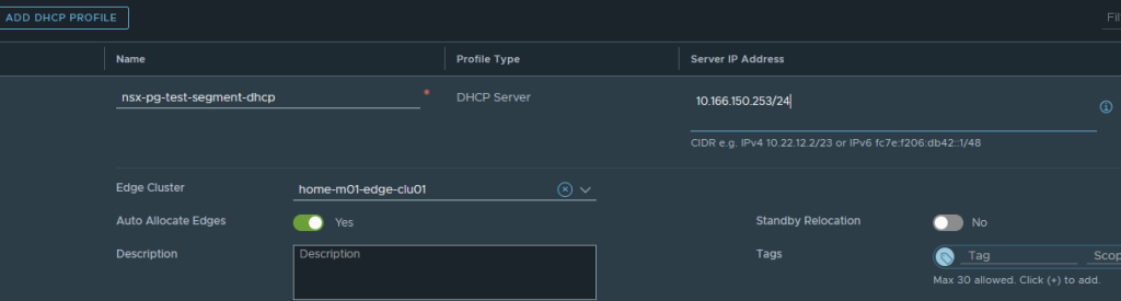
We will grant it DHCP from within NSX. To do this, go to networking > IP management > networking profiles > DHCP and click add DHCP profile.
Give it a name and enter an IP address in the CIDR we just added. I’ve used one address down from the gateway on the segment itself. Select the edge cluster, then click save.

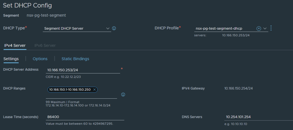
Go back to the segment, edit it and click the set DHCP config button.

Add the required configuration; the server address can be the same as the server address previously set in the DHCP profile. Also, set the DHCP range and DNS. Click apply, then save.
I will start a virtual machine to test. The segment will be selectable as a network for the virtual machine.

We can boot the VM and enable the NIC, which will issue an IP address from the NSX DHCP server.

This is Fedora, so if I press ALT + F2 I can get to the command line as root. I can then check the routing table and ping something on the internet.

If I look at the route table on my layer 3 router, I see the segment advertised.

Link Failure Testing
As a final step, I will pull cables out of the ESX host and show what happens. I’ve pulled uplink1 from the node, which flags this error.

The teaming and failover policy on the distributed port group is configured to failover to uplink2 automatically.

No errors were flagged inside NSX. If I look at the neighbours on the edge node, I see BFD is UP, and the relationships are established.
Some would argue that you want the failure to be handled within the layer 3 protocol. BGP is certainly capable of handling this; to do it, you would have to edit the teaming and failover policy and place the standby link into the unused state. This is identical to how you would configure block-based iSCSI in VMware.
This goes against the Broadcom documentation and recommendations for VCF, so do it at your own risk.
Here is what happens. First, I will change the teaming policy.

The edge node has disconnected the A path. The second B path is UP and happy, as this is tied to the uplink, which is still connected.

NSX will throw alarms.
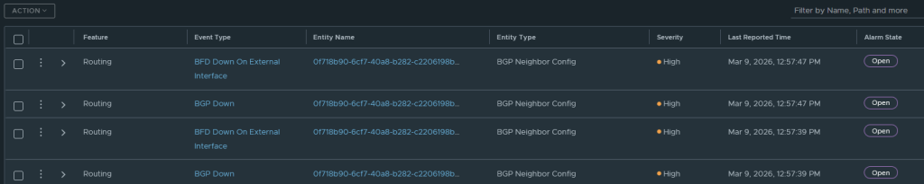
And the route table on the external router only shows paths to the surviving B VLAN. Notice the lack of “E” on connections 1 and 2.

In the route table, there is nothing for 10.166.106.1 or 10.166.106.2. Only the second uplink, or path B, is online and working.

Our test machine is happy with its connectivity.

Conclusion
That sums up a basic deployment of VCF with Classic NSX networking. Next, I will deploy Tanzu with this model, so it can be compared to VPC networking in my other deployment article.