This article will guide you through how to build a VMware Cloud Foundation solution in a single super tiny system.
Navigation
- Intro and thanks
- Build of materials
- Build Process Summary
- Configuring the MikroTik Router
- Building ESX
- SDDC Installer/Manager Customisations
- NVMe Tiering
- SDDC Installation
- Post Deployment Steps
- NSX Networking
- NSX Networking Tweaks
- NSX Confirm Routing
- VPC Networking Configuration
- What’s Next?
Intro and thanks
Although I currently work as the lead for a consulting practice in Alcester, I am, in the coming weeks, due to switch roles to work in the Private Cloud practice as a Principal Consultant within Computacenter. As with all technologies, I find the most valuable asset to learning is having the ability to tinker with the product and gain a deeper understanding. Although this is possible on customers’ systems to some extent, you’re usually far too constrained to freely play. Also, when needing to qualify difficult scenarios or replicate a customer’s complex problem, a test/dev/lab system becomes invaluable.
When I leave Simplify IT, I will be walking away from a dual Cisco UCS 5108 chassis with 16 blades and a plethora of technologies. Whilst I look to “link the fire” in my new home at Computacenter, I have taken it upon myself to build a home lab.
First off, a big thank you goes out to William Lam, who works for Broadcom directly. He has kindly created a fantastic set of resources with deep insight into undocumented or hard-to-find settings and has gone the extra mile in helping the community create laboratory systems for VCP9. Without his insight, things would have been trickier!
Build of materials
Below is a BOM which was used to create my VCF9 Lab. I took Williams’ idea and modified it a little. With the insane prices for DDR5, I did consider purchasing a prior-generation DDR4 system to get more memory capacity at less cost. However, with the running cost for the system I wanted, plus the NVMe tiering feature available in VCF9, I have managed to get what I need in one small, super tiny box. Hurrah! Here is what the final BOM looks like.
- 1 x Minisforum MS-A2 with AMD Ryzen 9955HX
- 1 x Crucial 128GB DDR5 SODIMM Kit (2 x 64GB)
- 1 x Samsung EVO 990 Plus 1TB for NVMe Tiering
- 2 x Samsung 990 EVO NVMe M.2 SSD 2 TB for vSAN and Local Storage
- 1 x MikroTik CRS310-1G-5S-4S+IN for switching and routing
- 2 x FS.com 0.5m 10G SFP+ DAC to connect the MS-A2 to the network at 10Gbps
- 1 x Icy Box Heatsink IB-M2HS to try and keep things cooler
The Minisforum MS-A2 is a small little beast; it’s advertised as only supporting 96GB, but it works fine with 128GB. Although with pricing going crazy due to AI, I think acquiring the 2 x 64GB DIMMs is tough. I was very lucky and got the last one for a sub-£700 price on Amazon Europe. The back of the unit supports 3 x M2 NVMe, two of which are cooled by a fan, and the third (where I placed the 1TB Samsung EVO 990 Plus) will support a heat sink, hence the Icy Box IB-M2HS. The unit overall runs fairly quietly, but once fully loaded, it does “spin up” from time to time. I went with 2 x 2TB for the other slots to give more options for larger workloads.
The MikroTik CRS310-1G-5S-4S+IN switch runs RouterOS on v7.21.1, which allows L2 VLANs as well as L3 BGP neighbour relationships for the NSX edges in the environment. The switch uplinks back to my Zen internet home router using the 1Gbps BASE-T port. I’ve configured WireGuard on the MikroTik switch as well, which allows me to VPN into the environment as I roam around, which is handy on those days away from home. If I can ever afford, or have a strong need for, more than one ESX host, the switch will support another 2 x 10Gb SFP+, i.e. one more ESX host! There is a CRS309-1G-8S+IN variant that has 8 x SFP+ as well, which would be an option if you want three. I have placed some 1Gb BASE-T transceivers in the other ports to connect to various other devices in my home network. RouterOS also supports DNS forward and reverse resolution out of the box, which saves a virtual machine and allows VCF to happily build itself.
I did originally order the following items, but unfortunately, the T705 is not recognised by ESX (thankfully, I got a refund). Additionally, the P510 was faulty on delivery and was corrupting files on write.
- 1 x Crucial P510 1TB M.2 2280
- 2 x Crucial T705 2TB NVMe 2280
ESX did install, but every attempt to upload a file, on investigation, the SHA256 hash was not right. After nearly a week of pain and slow debugging, I replaced the P510 with a Samsung NVMe, and the issue went away. With the corruption in place, VCF would build to a point but would then fail with random errors. It was a horrible experience, but I am very, very glad that I found the root cause and resolved it.
Build Process Summary
As part of writing this blog, I have uploaded the configuration files for VCF and MikroTik to a basic Github repo as they are easier to access and maintain. Below is a high-level, quick summary of the steps to get everything up and going. Later in this article, I will unpack the process for each of these steps.
- Configure the MikroTik router, including:
- DNS records for forward and reverse resolution
- NTP client and server.
- VLANs.
- IP addressing for VLANs.
- BGP configuration.
- BFD configuration.
- Wireguard Configuration.
- Boot the MS-A2 off a USB key with a kickstart file. Confirm the configuration for NVMe tiering to get a boost in memory from the default 128GB of system RAM.
- Deploy SDDC Installer/Manager onto the standalone ESX host – this will be converted to the final SDDC manager as part of the install.
- Configure SDDC Installer/Manager customisations over SSH to allow vSAN ESA using the NVMe drives and to permit a single host deployment.
- Connect to the VCF online depot using a token available on the Broadcom support portal. The first time I built this I chose not to use an offline depot as it adds more memory requirements to what is already pretty constrained with a single box. However for the rebuilds I did end up building a small Linux server and configuring it as a offline depot as per this article.
- Download the latest binaries for VCF 9.0.2 (at time of writing).
- Deploy VCF9 by uploading a JSON file into the deployment wizard.
- Connect to vSphere and configure “centralised connectivity” for NSX, which includes a two-node NSX edge cluster with a private transit gateway IP block and VPC external IP blocks.
- Confirm BGP neighbours come up and full adjacency is formed.
- Deploy a test VPC and Subnet into NSX through vSphere.
- Deploy a test VM into the NSX subnet, confirm the Mikrotik routing table has learned about the subnet and that the test VM can reach the internet.
Configuring the MikroTik Router
The simple way to first configure the MikroTik router is to download the WinBox utility, which will search the network and find the device. In order to find it, simply connect the standard copper Ethernet port to your existing home network. You can browse the configuration file in my GitHub repo and apply the bits you need for your environment.
I chose to set up a unique network behind the MikroTik with only VLAN 1 (PVID / untagged) bridging back to my existing home network. This created a more contained test environment. The ether1 port on the MikroTik is considered the external WAN interface and is set to DHCP for ease of use. The changes I made to my Zen home router were:
- Set DNS to the WAN address of the MikroTik (set by DHCP reservation on my home router), so by default, I also pick up the VCF resolution. The DNS server forwards to 1.1.1.1 and 9.9.9.9 for unknown zones.
- Create a UDP port forward for Wireguard so I can VPN in.
- Add a static route to my internal network behind the MikroTik router.
- Set the MikroTik ether1 port with a DHCP reservation so it’s easy to find, and so the static route created works over time.
The MikroTik is separated into the following VLANs. I wanted the environment to reflect a “customer” environment, hence separating out the VTEP networks for host/edge and also for host/VM management. This certainly isn’t required, but it also doesn’t make things that much more complicated.
| VLAN ID | Description | MTU | Firewall Address |
| 100 | Host Management | 1500 | 10.166.100.254/24 |
| 101 | VM Management | 1500 | 10.166.101.254/24 |
| 102 | VMotion | 9000 | 10.166.102.254/24 |
| 103 | vSAN | 9000 | 10.166.103.254/24 |
| 104 | NSX Host Transport | 9000 | 10.166.104.254/24 |
| 105 | NSX Edge Transport | 9000 | 10.166.105.254/24 |
| 106 | NSX Edge Uplink A | 1500 | 10.166.106.254/24 |
| 107 | NSX Edge Uplink B | 1500 | 10.166.107.254/24 |
Building ESX
For the ESX build, a bootable USB was created using Unetbootin, which helpfully does not format the existing USB stick; instead, it adds the required boot files to the existing partition. Once the process is complete, simply edit the EFI/BOOT/BOOT.CFG file on the USB drive and make kernelopt equal to “kernelopt=ks=usb:/esx01.cfg”. Once done, place the kickstart file from GitHub at the root of the USB drive.

At this point, you can boot the MS-A2 server with the USB key, and the ESX installer will boot and configure itself fairly quickly. Make sure you have connected both SFP+ ports to the MikroTik switch on any of the SFP+ ports. Once complete, you will be able to reach the ESX server and deploy the SDDC manager. I did this manually from ESX itself as it’s simple enough.
First, take the host out of maintenance mode, right-click on virtual machines and click Create/Register VM.

Select deploy a virtual machine from an OVF or OVA file.

Enter the name of the SDDC installer and select the OVA.

Select the local storage of the standalone ESX host.

Agree to the EULA.

Select the default VM network, which is already tagged with VLAN 101 from the kickstart script.

Enter the deployment details.
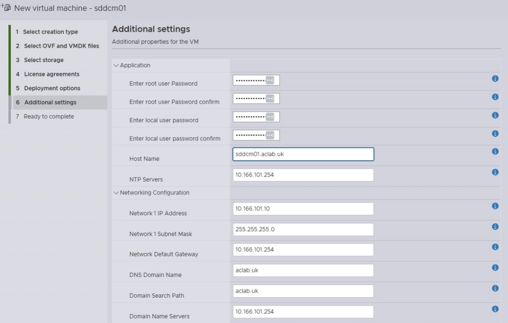
Review and click finish.

SDDC Installer/Manager Customisations
Once the SDDC installer/manager is deployed, three additional tweaks were made to the SDDC manager over SSH when logged in as vcf. They allow for a single host deployment and for the non-certified NVMe drivers to be claimed for vSAN ESA. The second line is for VCF 9.0.1 and 9.0.2, the third is for 9.0.0. I put both regardless.
su
echo "vsan.esa.sddc.managed.disk.claim=true" >> /etc/vmware/vcf/domainmanager/application-prod.properties
echo "feature.vcf.vgl-29121.single.host.domain=true" >> /home/vcf/feature.properties
echo "feature.vcf.internal.single.host.domain=true" >> /home/vcf/feature.properties
echo 'y' | /opt/vmware/vcf/operationsmanager/scripts/cli/sddcmanager_restart_services.sh
NVMe Tiering
Tiering was configured within the ESX kick start file, but in order to understand the steps better, you can also manually run the following commands. The first one will show you the NVMe devices. Fortunately, in my setup, the 1TB NVMe is a unique model, so it is obvious if you have multiple of the same, it can be trickier to work out what is what. To use tiering, the NVMe must have no partitions, so the one used for installing ESX will certainly have some, and you can easily spot that with the “ls” command below. Using partedUtil is another option if you prefer.
esxcli storage core device list
ls -lah /vmfs/devices/disks/
esxcli system settings kernel set -s MemoryTiering -v TRUE
esxcli system settings advanced set -o /Mem/TierNvmePct -i 100
esxcli system tierdevice create -d /vmfs/devices/disks/t10.NVMe____Samsung_SSD_990_EVO_Plus_1TB____________EEF2A35159382500
reboot
Following the reboot, we appear to have more “RAM” to play with. Memory is particularly low here, as I recently rebooted and have only since started vCenter and NSX. The following command also checks things out a little deeper. When reviewing stats, remember that tier1 is NVMe. Look at the tier1Consumed column and also note that memory tiering only tiers cold memory pages when there’s memory pressure. Active pages do not get moved to NVMe.
esxcli system settings advanced list -o /Mem/TierNvmePct
memstats -r vmtier-stats -u mb -s name:memSize:active:tier1Target:tier1Consumed:tier1ConsumedPeak:comsumed
As of right now, writing this, ESX is only tiering 1MB to NVMe, and used memory is at 109.39 GB. Hence, there simply isn’t enough pressure to need it.


SDDC Installation
Within GitHub, I have put a completed VCF planning workbook, which shows the low-level details of everything that was configured. You can reference this for the NSX configuration or just to generally understand the environment better. To deploy VCF, connect to the SDDC installer over HTTPS and deploy using the JSON spec on GitHub. You may want to modify it to suit your needs. The file is opinionated for this particular lab build. If you use different VLAN ID’s or CIDRs for your subnets, then it’s not going to work. Also, make sure you update the passwords!
Some other things I found out during my first rebuild:
- Don’t leave any virtual machines attached to anything but the default VM Network – these will break the SDDC deployment. The simple fix is to ensure they are removed from the inventory before starting. Anything on the default VM Network, i.e., an offline Depot server, will be migrated to the new distributed port group without issue.
- When you build the standalone ESX host, do not mess with the networking uplinks. You need to leave a single NIC uplinked to the default vSwitch0, in my case, this is with vmnic1, which is the first of the 10Gb Ethernet ports on the Minisforum MS-A2. The deployment also works if you use vmnic0 as the first NIC.
The JSON configuration will ensure the SDDC installer is converted to the SDDC manager as part of the install. This is handy as it saves deploying a separate installer outside of the environment (on a laptop, for example). The JSON spec will also exclude VCF Automation, mainly as I wanted to save resources and will come back to that part later.
During the installation, a failure will occur with vSAN; this will be due to only having a single node and FTT1 (failure to tolerate, i.e. RAID1) not being possible. To fix this, log in to vCenter > Storage and Profiles and modify the VCF created to have no data redundancy. Once done, click the retry button within the SDDC manager, and it will pick up again from where it failed.

Post Deployment Steps
Resource Savings
Once the install completes, edit the NSX manager appliance and remove the CPU and memory reservations. This will save some all-important memory overall for such a small lab system.


VCF Backups
Create a backup account on a Linux server, in my case I’m sharing an offline depot server with backups. This could be a separate backup server if you wish, however I’m sharing the same server to save resources. For instructions on how to build the offline depot server refer to this article.
This is the backup user setup, I’ve allowed an override for the ssh key auth just for the backup user.
## add user
useradd backup -d /home/backup -m
passwd -x 99999 backup
passwd backup
mkdir /home/backup/vcf-backups
sudo chown backup:root /home/backup -R
## allow password login for this one user
cat >> /etc/ssh/sshd_config <<EOL
# Allow password login for backup user
Match User backup
AuthenticationMethods password
PasswordAuthentication yes
EOL
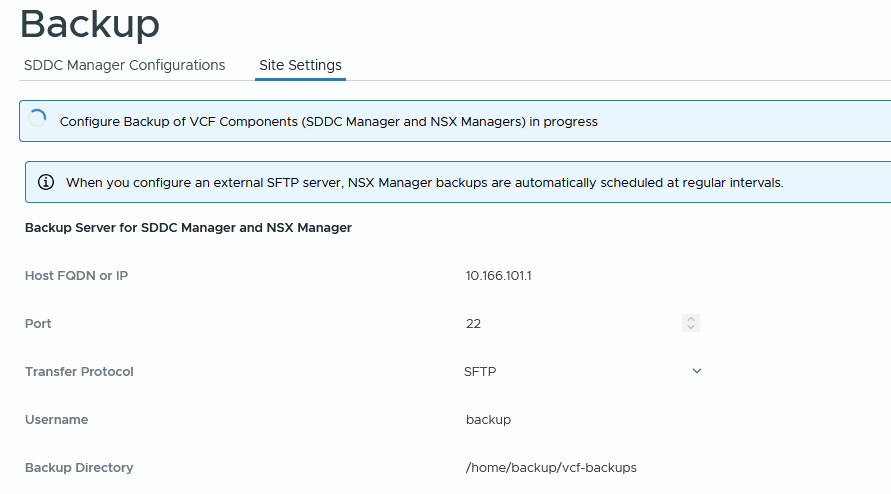
systemctl restart sshdLogin to SDDC manager, go to Administration > Backup > Site settings and enter the backup account password and encryption passphrase. Click save. The same task can also be done from VCF Operations > Administration > SDDC Manager > Backup Settings.

When you click save, the backup settings will be configured on the SDDC and NSX manager.
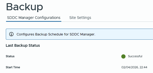
From the SDDC manager click backup now to test. The directory structure of the backup path looks like below. A sub folder is created for each backup type.

From NSX you will see backups.

Eventually, the backup will come back OK.
At this point, click edit on the schedule and configure according to your needs. For example.

From NSX manager > system > lifecycle management > backup and restore > edit the schedule and enable the config change backups. For example.

Connect to VCF Operations > Fleet Management > VCF Management > Settings > Backup and Restore > SFTP settings. Enter the SFTP settings for the backup server and user.

Under Backup Settings configure retention for each component.

Login to the vCenter VAMI portal and go to backup > configure. Create a backup schedule, for example.

Click backup now to test immediately instead of waiting for the schedule. The backup will go into a subfolder in the path specifed.

At this point you will have backups for:
- SDDC Manager
- VCF Operations
- NSX Manager
- vCenter including the Tanzu supervisor control plane
The final thing to do is ensure that the backup virtual machine is backed up and replicated offsite. Usually the 3-2-1 principal is followed, i.e. three copies of data, two on different storage media and a third off site.
NSX Networking
The VCF installer only deploys NSX Manager and configures ESX transport nodes. With this release, you can now easily complete the configuration from vCenter itself. If you click on the vCenter object, then go to Networks > Network Connectivity, you can complete a wizard which will deploy the NSX edge cluster nodes, external connectivity and BGP peering relationships. Click the configure network connectivity button to get started.

Select centralised connectivity to get full NSX configurations; distributed connectivity has no edge cluster, so no dynamic routing.

Select all on the next screen and click continue. We have the VCF workbook already pre-completed, so we know we have all the right information to carry out the configuration.

Enter the edge cluster name, form factor, and passwords, then click add.

Enter edge node 01 details. For this setup, make sure you untick the “use the host overlay network configuration from the selected vSphere cluster” This is because we are using dedicated edge transport VLAN 105, not VLAN 104, where the host is.
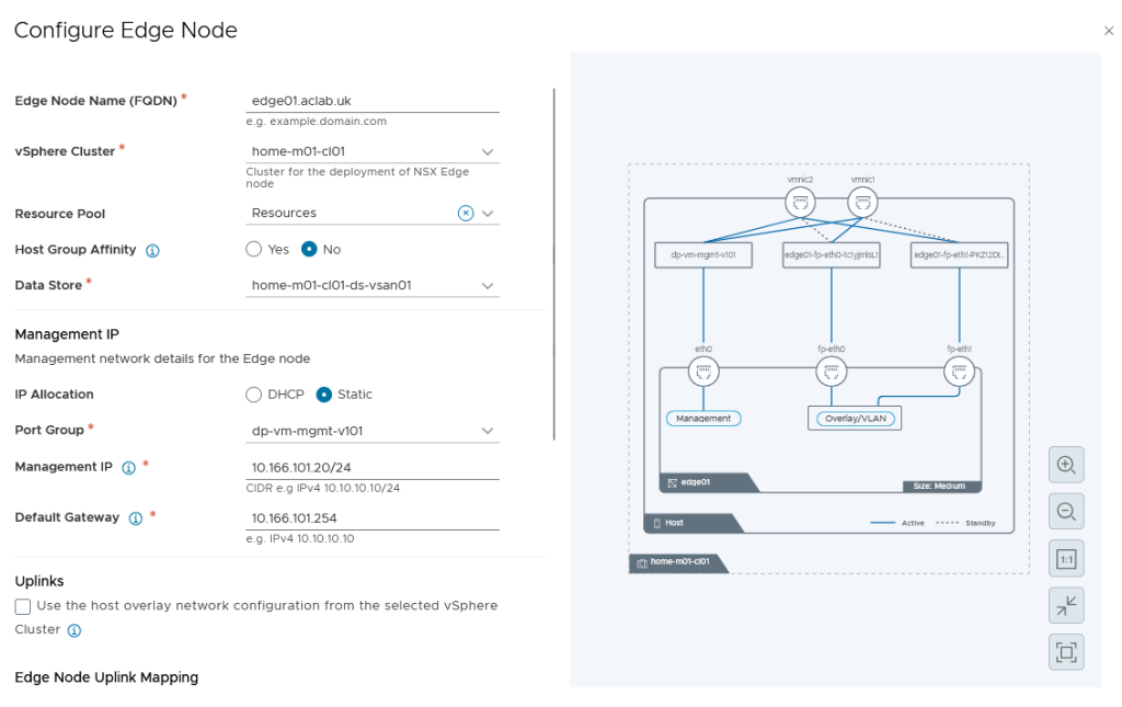
Select the pNICs, which it grabs from the vDS switch.

Create a new VTEP pool specifically for the edge nodes. I have chosen to do this as NSX customers that stretch their environments will also need a stretched edge VTEP pool (as the edge VMs float between sites). It doesn’t add much more complexity and more closely mirrors a production’s setup. Note that for this to work, the L3 interfaces as well as L2 VLANs must have sufficient MTU; mine are set to 9126 Jumbo.
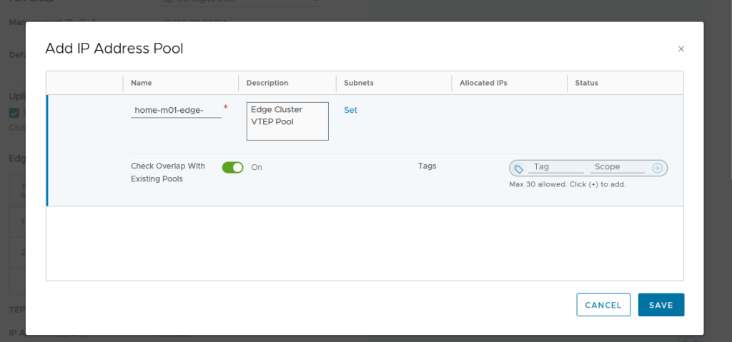
Click set on subnets, then add subnet > IP ranges. Click add then apply.

This will return to the address pool screen, where you can click save.

Click save to go back to the prior screen. Confirm the details, then click Apply.

Back on the edge cluster screen, click clone, and change the required details for edge node 02.

Click Apply to return to the prior screen, which will now show both edges.

Click next. Add the edge gateway details. We are using the name “parent” in case later we play with VRFs; if we do this, the VRF, in a way, becomes a “child”. This labelling helps with understanding.
We are using external block 10.166.108.0/24, which is not configured on the underlay but will be advertised to it from NSX. The external IP block must be able to be routable from the wider network.
For the private transit gateway IP blocks, I have selected 10.167.0.0/16.

Click set and enter details for the edge 01 gateway first uplink. We only need 1500 MTU as these are used for the VLAN uplinks to the underlay. Most environments will be routing at layer 3 using 1500 packets for this purpose. Our Mikrotik router is configured as such.
In an enterprise network, these addresses would usually be the top-of-rack switches or firewalls, which are enabled for BGP.

And the second uplink, then click apply.

This will go back to the prior workload domain connectivity screen. Click set on the gateway uplinks for edge node 02, then enter the details for the first and second uplinks.
If you are planning to use the edge cluster for VPC integration with Tanzu at a later date, be sure to select active/passive. You can only use active/active with Tanzu with the classic NSX topology type.
Click apply when the right mode is chosen.


Click Next on the workload domain connectivity screen.

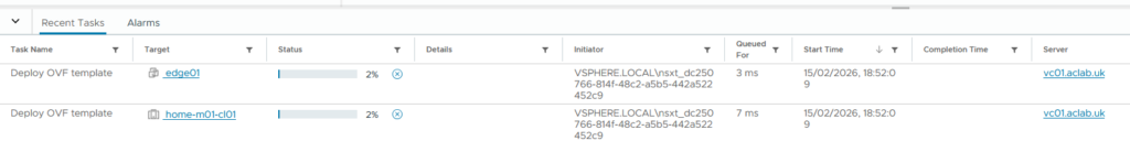
Review the settings and click deploy.

This will automatically deploy the edge nodes via the NSX manager. You can watch progress in vCenter and also in NSX Manager. It would be great if Broadcom would allow you to export the configuration to JSON for better automation.

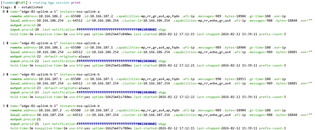
After around 5 minutes, the edges will boot and configure themselves. Once complete, validate BGP with the following commands run from the MikroTik switch. This command shows the BGP routes which have been advertised from the NSX edge cluster nodes.

This command shows what MikroTik call “connections”, but in usual BGP language, it is the BGP neighbour summary command. You can clearly see that the number of prefixes exchanged is 3.
NSX Networking Tweaks
The NSX deployment wizard from vCenter misses some configuration if you load NSX manager and edit the edge nodes one by one. Enable SSH and also configure the missing domain name, DNS and NTP servers; these are handy, particularly to get the right time stamps for logging.


NSX Confirm Routing
There are a few ways to confirm BGP from the NSX side. SSH to the edge node is my preferred route, you can also look at BGP neighbours in the GUI. When you see green, you are good!

To do this via NSX Edge CLI, log in with admin, then run the commands below. The output shows connectivity to both uplinks and the default route being advertised.
vrf ?     # find the SERVICE_ROUTER_TIER0 vrf number and use in the next command
vrf 1
get bgp neighbor summary
get route bgp
By default, there are no route maps, so all prefixes are permitted. As Microtik is advertising 0.0.0.0/0 NSX will know how to get to the internet. With the default NSX and Microtik firewall rules, workloads in NSX will be OK to get out and will be SNAT off the ether1 port and then again off your home lab router, so destinations on the internet know how to route back into your lab.
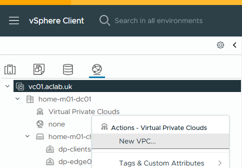
VPC Networking Configuration
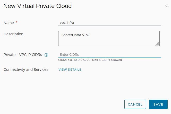
Once BGP is confirmed, the next step is to create a VPC and some subnets for workloads. You do this from vCenter > inventory > networking > right click virtual private clouds and select new VPC. vCenter will interact with NSX Manager to automate the required NSX components.
I have no plans to use private VPC CIDRs, so I have not added a CIDR. This can overlap between VPC’s and is used for networks which are routable only within each VPC.
Right-click on the VPC and click New Subnet.
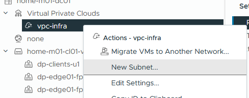
Enter the details for a server’s subnet, click next and finish. The three options are below. We are using public.
- Private – For subnets only reachable within this particular VPC
- Private – Transit Gateway – For subnets reachable from this and other VPCs but not beyond the transit gateway.
- Public – for subnets that need to be fully advertised outside of NSX.

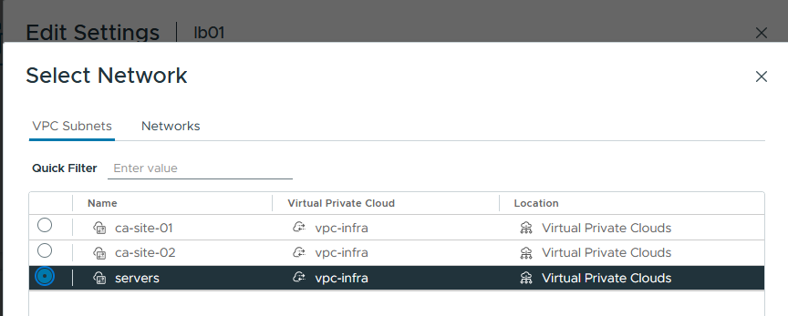
Create two more subnets; these have a specific use case for my PKI article.


Now attach virtual machines to the VPC subnets, for example.
Before testing, go into NSX manager > VPCs > Profiles VPC Service Profile and modify the default profile, adding in DNS and NTP servers. If DHCP is ever used on NSX, these will more than likely be needed.

I can now happily reach the internet from the VPC subnet on a test virtual machine. Hurrah! Remembering to try stateful TCP as well as ICMP, just in case asymmetric routing was at play!
What’s Next?
I plan to deploy Tanzu using VPC subnets. I have lots of exposure to VKS in the field, but have not yet played with VCF VPC integration. Although I currently still prefer a good old manual deployment of NSX, it appears Broadcom’s direction is towards the use of VPCs – so it had best be learned and understood fully.