This article explores an OpenShift networking pattern introduced in 4.19 that enables a deployment model closely aligned with common VMware NSX designs.
Users of NSX are very likely using core feature sets such as:
- Stretched L2 networks over L3 boundaries.
- Dynamic routing to get in and out of the SDN.
- Microsegmentation.
The main objective of this article is to provide an OCP replacement that meets the above requirements. OpenShift can go further, but that is a subject for another day. The pattern provided will allow for:
- Dynamic BGP routing to the underlay, replacing NSX edge clusters with Kubernetes native routers.
- Stretched networks to replace NSX segments. In my case, all nodes are in the same VLAN; however, they can also happily exist across layer 3 boundaries. The OVN CNI will take care of L2 over L3 with built-in GENEVE encapsulation between the nodes.
- Consistent IP addressing for VM Guest Operating systems. This is a big one and trips up many deployments where more open rule sets are required, i.e, Microsoft Domain Controllers that need a myriad of ports opened for client authentication. The use of K8 services and routes just doesn’t cut it.
- Microsegmentation to replace the NSX distributed firewall.
- Ability to deploy multiple tenancies with full network isolation.
- Containers and Virtual Machines that play nicely together.
Navigation
- Target Topology
- Introduction
- Control Planes
- Base Deployment
- GitOps Operator
- Application Set
- Dynamic Routing
- Stretched L2 over L3
- Consistent IP addressing for workloads
- Microsegmentation
- Tenant Isolation
- Containers and VM coexistence
- Conclusion
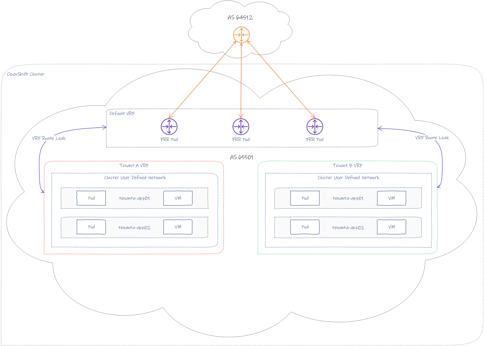
Target Topology
The topology combines the following key areas:
- Open Virtual Networking CNI.
- Cluster User-Defined Networks.
- Free Range Routing for Kubernetes via FRR-K8S.
- VRF per tenancy.
- Multiple namespaces per tenancy.
- Shared cluster-wide network(s) (CUDN) per tenant.
- Full tenancy isolation.
- BGP peering with external top-of-rack equipment.
- Ability to attach Containers and/or Virtual machines to a common tenant-based CUDN.
Introduction
My lab build consists of a single Minisforum MS-A2 with AMD Ryzen 9955HX and 128 GB RAM. The environment will be using nested virtualisation on VMware Cloud Foundation. I’m thinking of buying additional physical nodes for OCP; however, with the crazy memory and storage prices, I’m trying to ride things out and be inventive.
I hear Sam Altman’s 40% of global memory stock purchase order got canned, so hopefully the world markets will begin to settle again.
Control Planes
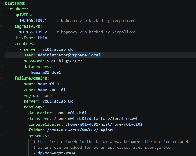
We will deploy a single failure domain with three control plane nodes on the latest OCP release. As per our install-config.yaml we have the following specified.
BGP peering will occur over the machine network on VLAN 109. If the top-of-rack equipment were, for example, Cisco VPC, you would want an uplink to each peer switch to create better resilience. In the lab, everything is on my lone MikroTik router.
Base Deployment
To deploy the cluster, download a copy of the install-config.yaml and modify it to your needs. Make sure you grab an up-to-date pull secret from the Red Hat OpenShift Hybrid Cloud Console. The end-to-end process is well documented in a prior article here. For this article, I’m going to focus more on the networking and security aspects.
The key difference from the other article is that we want to modify the manifests before we create the cluster. To do this, we run the commands below to drop a customised file in.
## setup base file, remember to modify as needed
mkdir ocp-region01
wget https://raw.githubusercontent.com/amayacitta/ocp-lab/refs/heads/main/ipi-vsphere/install-config-region01.yaml -O ocp-region01/install-config.yaml

## generate manifests and copy customisation to enable frr
./openshift-install create manifests --dir ocp-region01
wget https://raw.githubusercontent.com/amayacitta/ocp-lab/refs/heads/main/ipi-vsphere/custom-manifests/cluster-network-03-config.yml -O ocp-region01/manifests/cluster-network-03-config.yml

## deploy cluster
./openshift-install create cluster --dir ocp-region01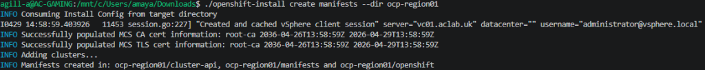
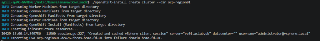
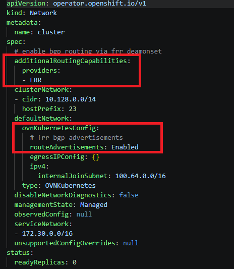
The bits we changed in the custom manifest are highlighted below. This enables the FRR and BGP advertisement capability. On vSphere IPI, this will work for containers or VMs. You don’t have to deploy OpenShift virtualisation.
At this point, the cluster will deploy; it takes around 20 minutes on my lab system. If you want to watch it build, I recommend opening multiple SSH sessions to the bootstrap and master-0 nodes. Then, run the commands below.
## run in seperate sessions to each node
watch crictl pods
journalctl -f
GitOps Operator
The intention is to deploy everything else from this point using ArgoCD, aka OpenShift GitOps. However, the first thing is to get ArgoCD itself deployed. With VMware Cloud Foundation, we do this with a Supervisor service or a Helm chart. With Red Hat OpenShift, we can use Helm, but I recommend using an Operator from the OpenShift software catalogue.
The manifest will enable the Argo CD instance to manage cluster-scoped resources, within the constraints of the default permission bindings, as described here. Later, we will extend the default permissions using an additional ClusterRoleBinding to allow all of our platform components to deploy without error.
## copy the kubeconfig for this regional cluster to the default path
cp ocp-region01/auth/kubeconfig ~/.kube/config
## or export the KUBECONFIG env if you prefer
export KUBECONFIG=ocp-region01/auth/kubeconfig
## check we have access
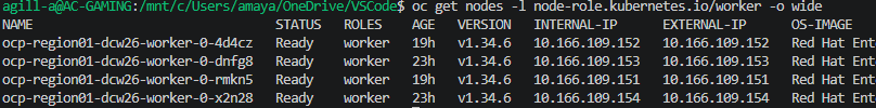
oc get nodes -o wide
## deploy the base gitops operator from static manifests
oc apply -f operators/openshift-gitops
Next, check that all pods are running.
## check argocd is running and grab the connection address
watch c get pods,route -n openshift-gitops -o wide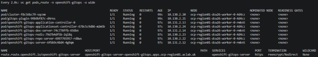
At this point, from a browser, we can log in to the ArgoCD interface using the address in the route. Note: I pre-trusted the issuing CA, which is why my browser didn’t throw an error.
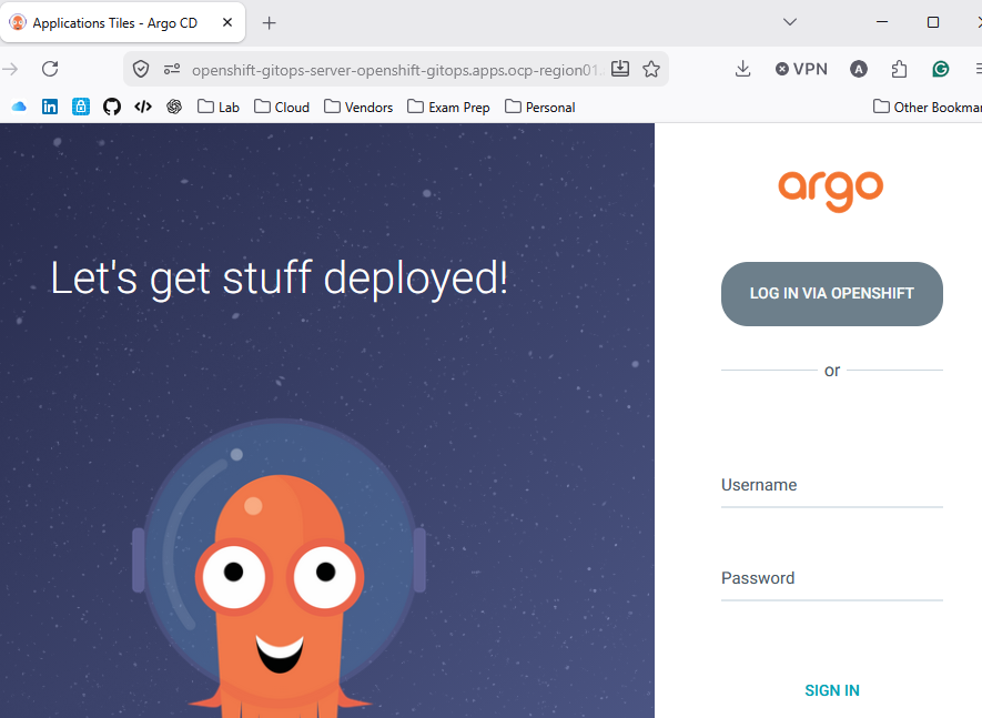
Click login via OpenShift to use OIDC, or enter admin and the password from the command below.
## grab default admin password
oc get secret openshift-gitops-cluster -n openshift-gitops -o jsonpath='{.data.admin\.password}' | base64 -d
At this point, we want to label the Argo Cluster. This is because we plan to use the Application Set pattern with labels to control which clusters applications are deployed to.
In a prior VCF Tanzu article, we had a centralised management cluster, which managed two regional clusters. In this OCP example, we just have the one cluster, but I’m thinking ahead and am laying the foundation for regional expansion later.
## set labels on cluster
ADMIN_PASSWD=$(oc get secret openshift-gitops-cluster -n openshift-gitops -o jsonpath='{.data.admin\.password}' | base64 -d)
SERVER_URL=$(oc get routes openshift-gitops-server -n openshift-gitops -o jsonpath='{.status.ingress[0].host}')
argocd login --username admin --password ${ADMIN_PASSWD} ${SERVER_URL} --skip-test-tls --insecure
argocd cluster set in-cluster --label type=workload --label region=region01

## confirm labels
argocd cluster get in-cluster --grpc-web | grep labels: -A 2
Application Set
At this point, we want to deploy an application set matching the above labels. This will deploy other platform components as Helm charts from a GitHub monorepo path. This pattern closely ties with what was previously done for Argo CD and Avi Multi-Cluster GSLB .
## deploy helm bootstrap chart
helm upgrade --install bootstrap ../helm-charts/ocp-bootstrap --namespace ocp-bootstrap --create-namespace

## confirm
oc get appset -n openshift-gitops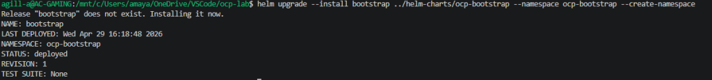
This will deploy a platform and tenant application set within the openshift-gitops namespace. The cluster will then begin bootstrapping the remaining components from a collection of Helm charts. You can very easily disable individual platform components by changing the enabled flag in the relevant values file to false.
The following platform components will be deployed by default.
- OpenShift Virtualisation with nested virtualisation enabled.
- An additional ClusterRoleBinding for GitOps. Note, as this is a lab, I have not followed the principle of least privilege and have granted Argo cluster-admin. This is obviously not recommended for production.
- Network manager state so the network configuration can be visualised and modified. This is needed if we want to play with localnets.
- FRR BGP configuration for peering to my MikroTik router.
- FRR Route Advertisements to advertise the CUDN to my home network.
The following tenancy components will be deployed by default.
- Cluster-wide user-defined networks.
- Tenant namespaces attached to the CUDN.
To fix the chicken-egg issue with CRDs, ArgoCD wave, hook and sync-option annotations are used. By way of example, the following applies to OpenShift Virtualisation. This sorts the deployment order as per the table below. i.e., OperatorGroup, Subscription and then HyperConverged only when the sync phase is successful.
| Component | Wave | Phase | Additional Annotations |
| kind: OperatorGroup | -2 | Sync | None |
| kind: Subscription | -1 | Sync | None |
| kind: HyperConverged | 0 | PostSync | SkipDryRunOnMissingResource=true |
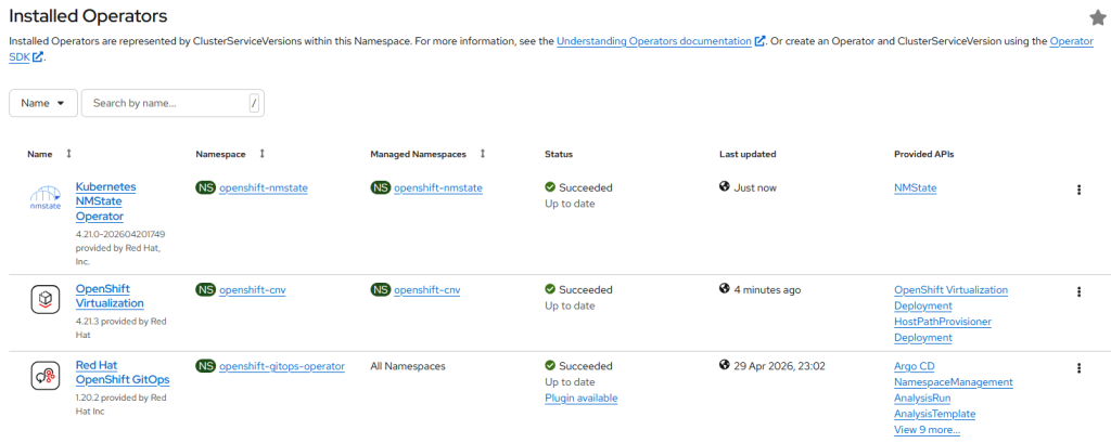
After a short while, we can look in the console and see successful operator deployments. If we change, for example, the subscription update channel or the update approval flag in Helm, then push the change into Git. After a few seconds, the change is reflected in the live environment.
We now have GitHub as our source of truth, which we can build on.
The last part of this article will unpack the NSX-like components one by one.
Dynamic Routing
A FRR-K8S router DaemonSet is configured within the openshift-frr-k8s namespace. This deploys a pod on every node; a FRRConfiguration CDR programs the BGP configuration. In our case, this only applies to worker nodes using a matchLabel. Master nodes are ignored and therefore have no neighbour information, BGP router, etc.
This diagram summarises what we will configure. This isn’t an exhaustive diagram, but hopefully it helps visualise dependancies.
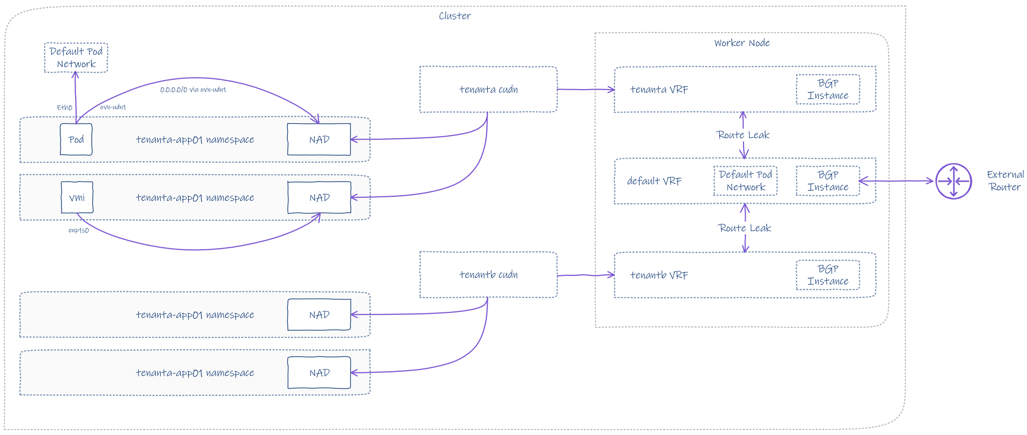
We won’t be placing any workloads on the master nodes due to taints and also for stability reasons. The control plane nodes are busy enough with all of the control plane and infra pods. In my experience, converging the master and worker nodes becomes problematic fairly quickly; I don’t recommend it.
To review the BGP configuration, we can review the FRRNodeState CRD using the commands below. I will unpack this further in the sections that follow.
## get node state for all nodes
oc get FRRNodeState

## get node state for a specific worker
oc get FRRNodeState ocp-region01-dcw26-worker-0-4d4cz -o yaml
Default VRF
Each node belongs to a default VRF, which has its own BGP configuration automatically generated and inserted into each FRR node pod. If you refer back to the topology diagram at the top, you will notice that AS 65501 is the OCP cluster and AS 64512 is the external router, which, in my case, is a MikroTik running RouterOS.
Route leaking is importing prefixes from tenant A and tenant B into the default VRF. This allows the tenancies CUDN’s to be advertised and for packets to route in and out.
There are also route maps to constrain what is permitted into the BGP RIB. The routing information base holds all possible paths for each prefix. It’s from this that the BGP best algorithm selects the “best path” and adds it into the routing table.
Additionally, BFD is configured to improve failover detection and convergence. This also has to be enabled on the external router to take effect.
    router bgp 65501
     no bgp ebgp-requires-policy
     no bgp default ipv4-unicast
     bgp graceful-restart preserve-fw-state
     no bgp network import-check
     neighbor 10.166.109.254 remote-as 64512
     neighbor 10.166.109.254 bfd
     neighbor 10.166.109.254 bfd profile bfd-default
     !
     address-family ipv4 unicast
      network 10.166.250.0/24
      network 10.166.251.0/24
      neighbor 10.166.109.254 activate
      neighbor 10.166.109.254 route-map 10.166.109.254-in in
      neighbor 10.166.109.254 route-map 10.166.109.254-out out
      import vrf tenanta
      import vrf tenantb
     exit-address-family
     !
     address-family ipv6 unicast
      import vrf tenanta
      import vrf tenantb
     exit-address-family
    exit
Tenant A VRF
Each CUDN becomes a VRF within the worker node. The default route table is also imported into Tenant A’s VRF table.
    router bgp 65501 vrf tenanta
     no bgp ebgp-requires-policy
     no bgp default ipv4-unicast
     bgp graceful-restart preserve-fw-state
     no bgp network import-check
     !
     address-family ipv4 unicast
      import vrf default
     exit-address-family
     !
     address-family ipv6 unicast
      import vrf default
     exit-address-family
    exit
Tenant B VRF
The default route table is also imported into Tenant B’s VRF table.
    router bgp 65501 vrf tenantb
     no bgp ebgp-requires-policy
     no bgp default ipv4-unicast
     bgp graceful-restart preserve-fw-state
     no bgp network import-check
     !
     address-family ipv4 unicast
      import vrf default
     exit-address-family
     !
     address-family ipv6 unicast
      import vrf default
     exit-address-family
    exit
Prefix Lists
The following prefix lists are auto-generated.
    ip prefix-list 10.166.109.254-allowed-ipv4 seq 1 permit 10.166.250.0/24
    ip prefix-list 10.166.109.254-allowed-ipv4 seq 2 permit 10.166.251.0/24
    ip prefix-list 10.166.109.254-inpl-ipv4 seq 1 permit any
    !
    ipv6 prefix-list 10.166.109.254-allowed-ipv6 seq 1 deny any
    ipv6 prefix-list 10.166.109.254-inpl-ipv4 seq 2 permit any
Route Maps
The following route maps attach to the router instances and prefix-lists above. These filter prefixed being learnt and advertised. If you search this page for the route-map name, then scroll up, you will see how they attach to each router instance.
    route-map 10.166.109.254-out permit 1
     match ip address prefix-list 10.166.109.254-allowed-ipv4
    exit
    !
    route-map 10.166.109.254-out permit 2
     match ipv6 address prefix-list 10.166.109.254-allowed-ipv6
    exit
    !
    route-map 10.166.109.254-in permit 3
     match ip address prefix-list 10.166.109.254-inpl-ipv4
    exit
    !
    route-map 10.166.109.254-in permit 4
     match ipv6 address prefix-list 10.166.109.254-inpl-ipv4
    exit
External Router
In order for prefixes to exchange from the SDN to the outside world and vice versa, we need to configure a BGP instance and neighbour relationships. Most vendors these days will allow something like Cisco BGP Peer Groups, so you can enter 10.166.109.0/24 for the BGP neighbours.
Peer groups help because nodes are managed using MachineSets and will be scaled, removed, and replaced over time. If we attach to individual IP addresses that change, it will be challenging to keep things working correctly.
For MikroTik RouterOS 7.21.3, there is currently no way to configure a network CIDR for the neighbours; I can only add individual addresses. A simple route would be to add the entire DHCP range for VLAN 109, perhaps shrinking it a little and lowering the lease time. Given it’s just a lab, I’m going to grab the worker addresses and add them directly.
The full BGP configuration on the router is as follows. Note, we are advertising connected subnets from the outside into the SDN. Although we have a default route already, this will help with understanding when digging deeper.
## bgp configuration for region01 ocp
/routing bgp instance
add as=64512 disabled=no name=ocp-uplink router-id=10.166.109.254 routing-table=main vrf=main

/routing bgp connection
add as=64512 comment=ocp-uplink connect=yes disabled=no instance=ocp-uplink local.address=10.166.109.254 .role=ebgp name=ocp-uplink-a output.redistribute=connected remote.address=10.166.109.151 .as=65501 routing-table=main use-bfd=yes vrf=main
add as=64512 comment=ocp-uplink connect=yes disabled=no instance=ocp-uplink local.address=10.166.109.254 .role=ebgp name=ocp-uplink-a output.redistribute=connected remote.address=10.166.109.152 .as=65501 routing-table=main use-bfd=yes vrf=main
add as=64512 comment=ocp-uplink connect=yes disabled=no instance=ocp-uplink local.address=10.166.109.254 .role=ebgp name=ocp-uplink-a output.redistribute=connected remote.address=10.166.109.153 .as=65501 routing-table=main use-bfd=yes vrf=main
add as=64512 comment=ocp-uplink connect=yes disabled=no instance=ocp-uplink local.address=10.166.109.254 .role=ebgp name=ocp-uplink-a output.redistribute=connected remote.address=10.166.109.154 .as=65501 routing-table=main use-bfd=yes vrf=main
Once configured, we can check to see if things are working correctly. From MikroTik, we can see both CUDN networks being advertised across VLAN 109. It’s worth knowing that packets will flow in via the Active path and will then reach the destination through the SDN. You could consider this an unoptimised path; there is no way to track what address is where, the advertisement is global across all FRR pods.
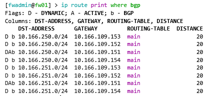
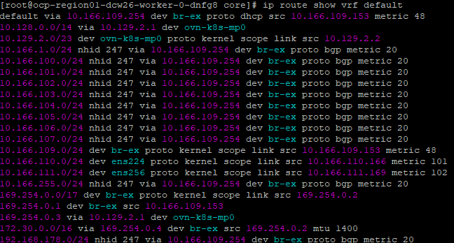
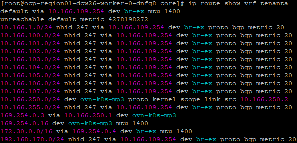
From the default VRF on the nodes, we can see the connected prefixes.
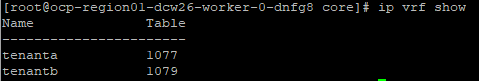
From Tenant A, we can see the leaked routes.
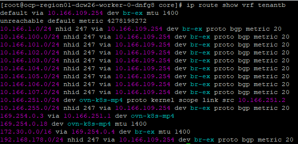
Ditto for Tenant B.
We can now directly reach the VM’s or pods as the CUDRs are advertised. Here is an example pod.
Stretched L2 over L3
The CUDN for tenanta and tenantb are, by default, cluster-wide overlay networks. They are available to every node in the cluster. IP addressing follows the virtual machine, wherever it goes, which is one of the main advantages of NSX segments.
As with NSX transport nodes, each Kubernetes node (of all roles) is a VTEP endpoint, with GENEVE tunnels automatically formed and used as required. Outer UDP encapsulation respects the original packet and can happily flow across layer 3 boundaries. Once the packet reaches its destination VTEP endpoint, the outer UDP packet is stripped, and the original reaches its final destination. This means your nodes can be in entirely different layer 3 networks, and mac-to-mac communication still occurs as if it were within the same broadcast domain.
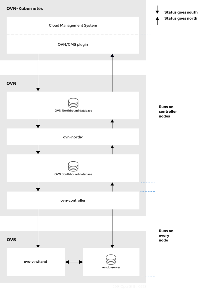
The OVN architecture contains many components. The northbound database holds the intended state of the OVN environment as a whole; configuration data flows north-to-south, passing it to Kubernetes node OVN-controllers via the southbound database, ultimately being configured as OVS configuration etc.
OVN is represented by the diagram, taken from OCP’s documentation. An additional read is the OVN manual page here. The following YouTube video will also explain why Red Hat adopted OVN for OpenShift over its predecessor.
Consistent IP addressing for workloads
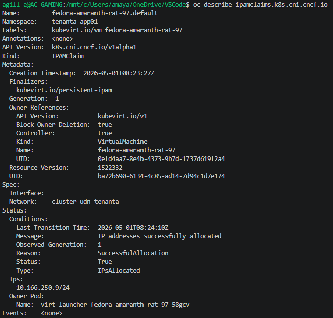
Each of the configured CUDNs is configured with IPAM and a persistent lifecycle setting. One would assume this is akin to public cloud networking, which, in the case of Azure, issues permanent (until the VM is deleted) IP addresses against virtual network subnets. The manual says:
Lifecycle controls IP addresses management lifecycle. The only allowed value is Persistent. When set, the IP addresses assigned by OVN Kubernetes will be persisted in an `ipamclaims.k8s.cni.cncf.io` object. These IP addresses will be reused by other pods if requested.
If we describe the ipamclaims object, we only see one for the VMI launcher pod. The containers we also attached, although they are within the same CUDN, do not have any IPAM claim. This is because the IPAM controller is specific to KubeVirt, which is a major component of OpenShift Virtualisation.
So what does this mean for containers? Well, let’s see. Currently, I have two native container-based pods and a Kubevirt launcher pod. The CUDN IPAM addresses are as follows.
| Resource | Address |
| Application pod 01 | 10.166.250.7 |
| Application pod 02 | 10.166.250.4 |
| KubeVirt launcher pod / VMI | 10.166.250.9 |
I drained the nodes they were running on, causing everything to reschedule on other nodes.
oc adm drain ocp-region01-dcw26-worker-0-4d4cz --ignore-daemonsets --delete-emptydir-dataAnd what happened? Well, the containers were obtained with a fresh address. However, the virtual machine maintained its address. If you look at the upstream GitHub readme, this is indeed behaving correctly. Even with the rescheduling of the launcher pod, the IP address sticks because of the ipamclaims object, which is explicitly bound to the virtual machine.
| Resource | Address |
| Application pod 01 (recreated) | 10.166.250.14 |
| Application pod 02 (recreated) | 10.166.250.16 |
| KubeVirt launcher pod / VMI | 10.166.250.9 |
Containerised applications are happy with dynamic addressing; you normally front them with services, Gateway API or Ingress, and Port exposure is minimal. This is normal behaviour for the default pod network, which is usually where application containers get their addressing.
Virtual machines are usually persistent and may rely on complex port exposure. For example, with Microsoft Active Directory, you want the guest IP address to be the real address on the network, and for it to be consistent. This rules out using L3 overlay or Pod Network, which both have individual CIDRs per node. This would mean changing the address when rescheduling or live migrating.
To my mind, this only leaves two possible routes, CUDN as configured above or localnets.
CUDN on an L2 overlay offers the benefits of an NSX-like stretched segment, which has distinct advantages over traditional VLANs. You can, of course, stretch VLANs, but once multiple geographies or larger / more complex environments are involved, I think using a L2 overlay is a better option.
I hear EVPN is also on the roadmap for OVN. This will allow you to extend the OVN overlay to the external datacenter network. Something that NSX can already do today.
Microsegmentation
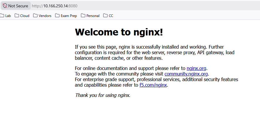
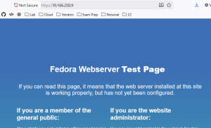
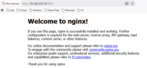
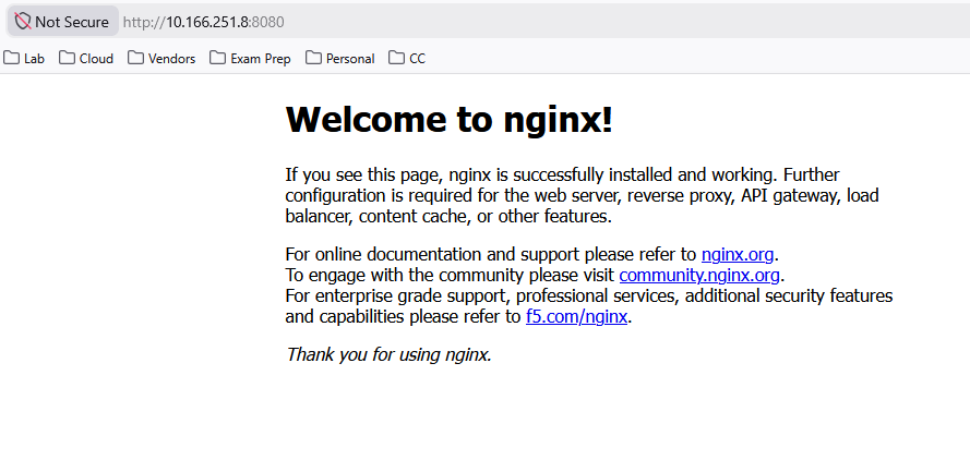
To test this out, we have our two NGINX containers and our VM, to which I’ve put a default install of Apache. I can happily access the web pages from my machine. Remember, this is possible as the CUDN is being advertised by BGP.
Fedora VM on HTTP port 80
NGINX Container on HTTP port 8080
I will now apply this basic block policy which will stop all ingress and egress traffic in the namespace.
cat <<EOF | kubectl apply -f -
apiVersion: networking.k8s.io/v1
kind: NetworkPolicy
metadata:
  name: default-deny-all
spec:
  podSelector: {}
  policyTypes:
  - Ingress
  - Egress
EOF
Both websites are now down externally; if I also try internally from the VM inside the same network, I get the same result.
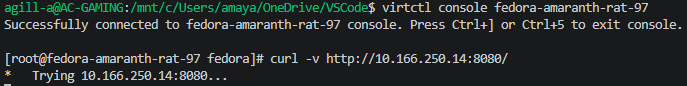
If I remove the network policy, everything works again.
This is a crude but effective example of how to constrain networking within the same namespace. Remember, Network Polices are additive, so in addition to default blocks, you would also want to add policies allowing the ports required for the application to function.
Tenant Isolation
Without any network policies in place, can we reach the pod in Tenant B from Tenant A?
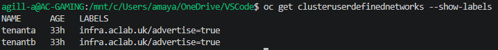
The answer is no, because each of the CUDNs is in a specific VRF; you cannot route between them, even with the leaking we configured earlier. This means we get full tenant isolation per CUDN, with the flexibility of multiple namespaces.
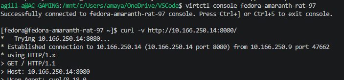
Below is me trying to curl NGINX in Tenant B from Tenant A. No connection is possible.

However, it is possible from the external network as both CUDN CIDRs are advertised with the following label.
Containers and VM coexistence
OpenShift has supported KubeVirt since 2022, allowing full co-existence of Virtual Machine workloads, alongside containers on the same bare metal nodes. This is a core feature set as long as you have at least Red Hat OpenShift Kubernetes Engine, which supports both workload types.
With our CUDN configuration, we are using Mutus CNI, which allows for multiple networks to be attached to the pod. If we dig deeper into a specific application container, we can see how this works.
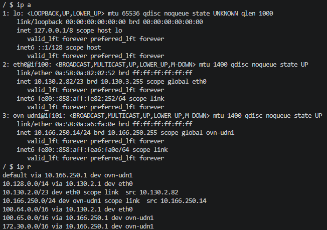
The container has a default eth0 which resides on the normal pod network; this is by default a /23 per node, carved out from the clusterNetwork. In addition, the CUDN is attached via a second NIC.
The route table shows the default being across the CUDN, not the Pod Network. This is because we have configured a Primary network in both the CUDN and the Namespace.
There are, however, some caveats as outlined in the documentation here. I’ve copied some and put some comments on key ones, which relate to Virtual Machine challenges I’ve faced in the field.
- DNS lookups for pods resolve to the pod’s IP address on the cluster default network. Even if a pod is part of a user-defined network, DNS lookups will not resolve to the pod’s IP address on that user-defined network. However, DNS lookups for services and external entities will function as expected.
This is probably not an issue, as most people resolve through services which front the pods. For the virtual machines, the guests have real, routable IPs; for Active Directory, you will override the DNS server to point to the domain controllers. For K8 to AD, you can rely on CoreDNS forwarders to resolve the AD DNS name, rather than try to reach it internally using a *cluster.local address.
- When a pod is assigned to a primary UDN, it can access the Kubernetes API (KAPI) and DNS services on the cluster’s default network.
This is true; however, you can control this behaviour with Network Policies.
Conclusion
This concludes our journey with CUDR’s and BGP. I hope this helps when looking to migrate from VMware NSX to OpenShift. Best of luck, and please do reach out if you have any questions or need help with anything.