
In this second of a two-part series, we will explore deploying Tanzu with AVI Load Balancer with NSX VPC networking. In part #1, we deployed AVI with NSX integrated load balancer.
Tanzu built in this way is arguably the most modern and feature-rich pathway. Unfortunately, AVI is not bundled with VCF; it’s a paid add-on. Licensing is based on the data plane, not the control plane. There are various licensing scenarios, such as Bandwidth, Per-App, Bare Metal, etc. Details are fleshed out in the main administrator’s guide here.
Navigation
- Introduction
- Target Topology
- Preperation
- Deploy AVI HA Control Plane
- Deploy AVI Single Node Control Plane
- Configure AVI Control Plane
- Configure NSX Cloud for NSX VPC Networking
- Deploy the Tanzu Supervisor
- Validate the Tanzu Supervisor
- Additional Namespaces
- AVI DNS Setup
- Deploy vSphere Kubernetes Service
- AVI Kubernetes Operator
- Deploy vSphere Pod Application
- Final Topology
- Conclusion
Introduction
As a load balancer, AVI is up there as one of the best; it has a fully split control/management and data plane with linear scaling and full support for VCF, public/private cloud and bare metal. There are broad integration guides for VMware, Google, Linux, OpenStack, Azure, KVM, Cisco ACI, Oracle, AWS and Nutanix. It supports WAF, GSLB and other enterprise-ready features.
You can integrate AVI into VCF in two ways; in either case, there is always a 1-1 relationship between NSX Manager and the AVI control plane.
- Deploy a dedicated NSX manager and AVI control plane cluster into each workload domain. This is referred to as a 1:1 architecture.
- Deploy a single NSX manager and AVI control plane cluster into the management domain and use this to deploy AVI data plane virtual machines, called service engines, to each workload domain. This is referred to as a 1:N deployment.
In my lab, as per my VCF9 Lab article, I have a management domain with a single host, so there isn’t much choice here. I can only deploy to the management domain, and have no other workload domains to deploy to or share with.
Target Topology
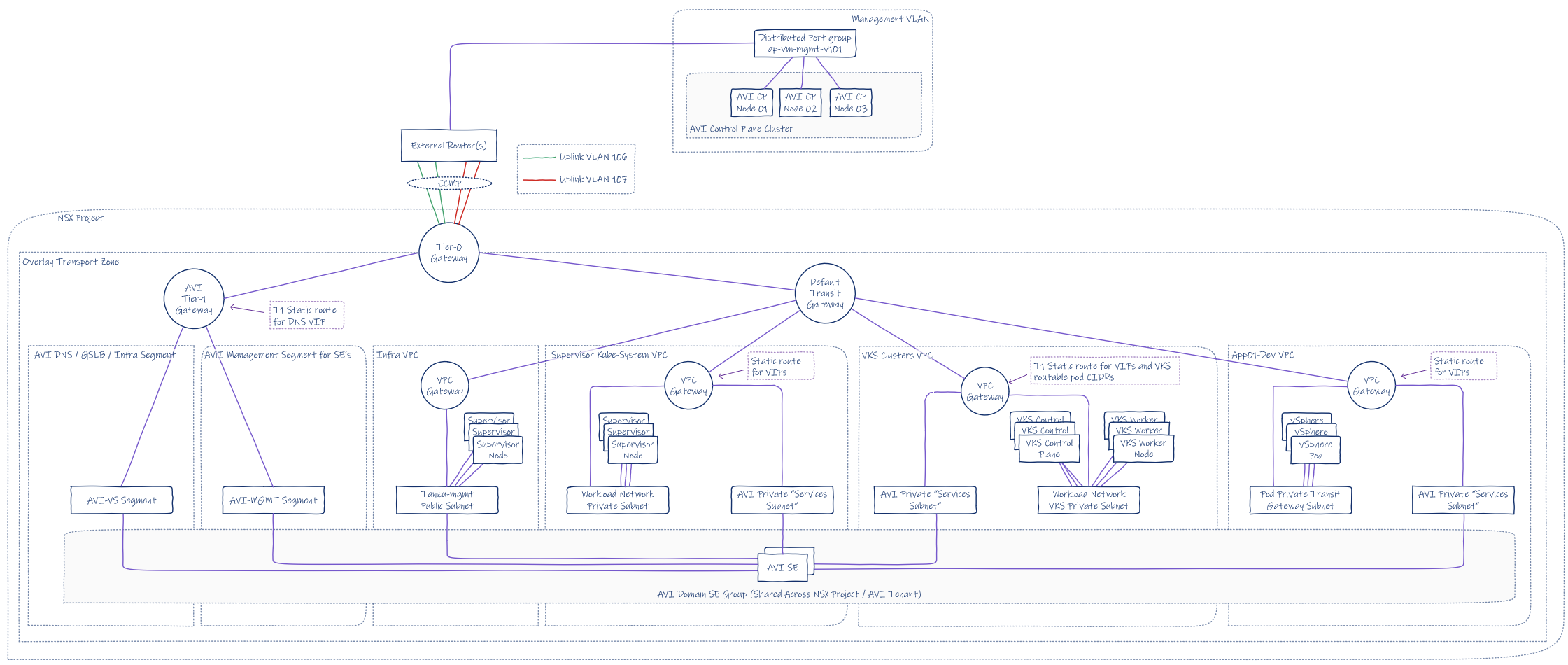
This is the target topology for this article. I’ll explain each step to get there.

Preperation
First, we pre-create DNS records. For my lab, I added the following to my MikroTik router. This adds both forward and reverse records automatically. The deployment relies on DNS resolution to allocate the main AVI VIP.
## add forward and reverse records
/ip dns static
add address=10.166.101.27 comment="AVI CP VIP" name=avi.aclab.uk type=A
add address=10.166.101.28 comment="AVI VP 01" name=avi01.aclab.uk type=A
add address=10.166.101.29 comment="AVI VP 02" name=avi02.aclab.uk type=A
add address=10.166.101.30 comment="AVI VP 03" name=avi03.aclab.uk type=A
Before creating a workload cluster, we must add the AVI bundle to the SDDC manager. This will allow the selection of the latest version when adding AVI to the workload domain via SDDC manager.
The AVI bundle contains three files, two are present on the AVI GitHub page.
The third, AVI OVA is downloaded from the Broadcom support portal.
First, download the JSON and Sig files. At the bottom of the JSON file, you will find the latest supported version. Take note of the productVersion and fileName.
At the time of writing this article, productVersion 31.2.1-25015167 was the latest. This is one release behind what’s available on the Broadcom download page. Once you know what the version is, download the related OVA file from the Broadcom website.

Next, download the AVI bundle bash script from the AVI GitHub repository. I also had to run the following commands from SSH on the SDDC manager as per KB 394427. Even on VCF 9.0.2, without these permission tweaks, I was getting the following permission failures.

## fix permission errors with the avi bundle script
ssh vcf@sddcm01.aclab.uk
su
chown -R vcf_lcm:vcf /nfs/vmware/vcf/nfs-mount/bundle/
chmod -R 0777 /nfs/vmware/vcf/nfs-mount/bundle/
From a Linux Bash shell, run the following. In my case, I used my Fedora WSL instance.
## change to my download path where the sig, json and ova files are
cd /mnt/c/Users/agill/Downloads

## download the script and make executable
wget https://raw.githubusercontent.com/avinetworks/devops/refs/heads/master/tools/vcf/vcf_tools.sh
chmod +x vcf_tools.sh

## run
./vcf_tools.sh
When you run the script, follow the prompts. Remember to use ./pvc.json and ./pvc.sig for the file paths. Here is the complete process.

From the SDDC manager GUI, you will see the successful bundle upload in the task history.

Deploy AVI HA Control Plane
Only follow these steps if you have enough compute capacity and three hosts. You will need 96Gb of RAM and three hosts for the DRS anti-affinity rules. If you’re running a small two or one-node lab, please follow the steps in the deploy AVI single-node control plane section instead.
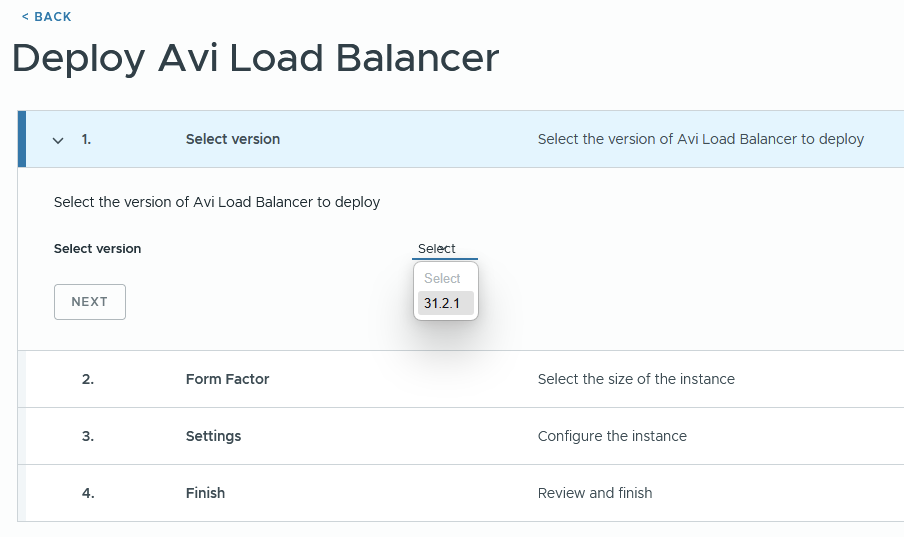
From the inventory > workload domain section of SDDC manager, click the workload domain. Under actions, you can deploy AVI Load Balancer.

For VCF 9.0.2, I had the following issue.
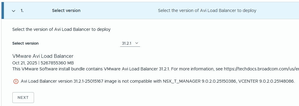
If you check the product interoperability matrix, it should be supported. Unless I need my glasses.


I repeated the above steps, but for version 31.1.2, and there was no compatibility issue. Click next.

Select the required size. Follow the guidance in the table below. Small will scale up to 200 service engines. Note that whatever you choose, three control plane nodes will be deployed for HA reasons. Click next.
| CPU/ Memory Allocation | Small (6 CPUs/ 32 GB) | Large (16 CPUs/ 48GB | X-Large (16 CPUs/ 64 GB) |
| Base processes | 19 GB | 24 GB | 32 GB |
| Log analytics | 13 GB | 24 GB | 32 GB |
| SE Scale | 0-200 | 200-500 | 200-500 |

Complete the details referencing the DNS records added earlier. DNS resolution of the AVI FQDN is what determines the VIP address. Click next.
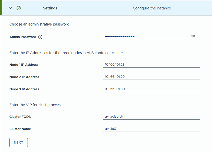
Review and click Start Deployment.

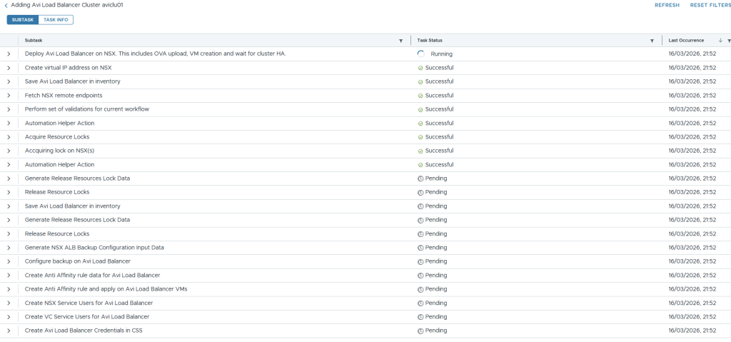
The task page in SDDC Manager will show the progress of the deployment.

If you click the task itself, you will get more granular detail about its progress.
Under NSX manager > system > appliances, you will notice the VIP for AVI is configured, and the controllers are being deployed.

vSphere will show the OVA deployments.

Which go into an unmarked folder. Once deployed, you can move them wherever you like. I placed mine under the VCF folder.

The deployment put a lot of strain on my lonely MS-A2 host. To complete the install, I had to shut down VCF Ops and one of the edge nodes. The system was running hot and throwing high active DRAM memory usage.

Tier1 memory on NVMe was churning away, which is shown with memstats.

From SSH on the first AVI node, I could see it build the cluster.
ssh admin@avi01.aclab.uk
shell
show cluster status
The control plane VIP was active, and I could see the last node joining the cluster.

Should you have three nodes, everything will deploy successfully, and the following will be achieved.
- Automatic creation of a three-node control plane cluster
- Backup will be configured for the SDDC manager.
- Anti-affinity DRS rules will be added against the compute cluster in vCenter
- NSX and vCenter service users will be added and configured
Unfortunately, the SDDC manager expects more than one node and bombs out with the following error. You’ll only see this if you have a single host.
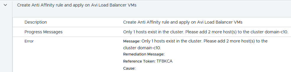
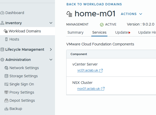
Within the workload domain services, there is no AVI, and there is no fix I know of.
If you have a single host, hopefully you didn’t get this far and have already completed the single-node deployment as outlined below. If needed, go to the workload domain > actions > remove AVI load balancer and then complete the steps in the single node control plane section below.

Deploy AVI Single Node Control Plane
If you have a single node in your environment, you will want to follow William Lam’s tip. As per his single-node AVI load balancer article, we add the following to the SDDC manager.
echo 'feature.vcf.vgl-41078.alb.single.node.cluster=true' >> /home/vcf/feature.properties
reboot
Download a slightly modified version of his PowerShell script, which will configure a single node control plane node via the SDDC manager. The updated script includes parameters, making it easier to reuse in different environments.
Run the script and complete the prompts. DNS resolution of the AVI FQDN is what determines the VIP address.
.\deploy-single-node-avi.ps1
This deploys a single node and completes in under 10 minutes.

Configure AVI Control Plane
Log in to the AVI control plane and complete the wizard. Enter a backup passphrase. DNS resolver and search domain. Click next.

Enter email details if needed. I chose to disable this.

Under multi-tenant, if you leave the defaults, your networking and service engines will be inside a common “admin” tenant and VRF. This is configurable later under system settings. For my lab, I only have one management domain, with no workload domains, so I have left it at the default. Tick the setup cloud after box and click save.
There are some decent sections in the official documentation which explain tenants very well. Read this and this.

Go to administration > licensing and set to the enterprise tier.

Because we have deployed the AVI control plane through the SDDC manager, AVI will have already been onboarded into NSX. There is no need to complete the onboarding workflow; instead, we can simply check it with the command below.
Note the status of DEACTIVATE_PROVIDER and also the certificate used, which is the default self-signed one. This will need to change before we deploy the supervisor cluster.
curl -k -u 'admin:<changeme>' --location --request GET https://nsx01.aclab.uk/policy/api/v1/infra/sites/default/enforcement-points/alb-endpoint
Configure Certificate Trust
Next, we install a new AVI portal certificate and roots. Go to Templates > Security > SSL/TLS Certificates > Create > Root/Intermediate > Import your own PKI root and issuing certificates. Click validate and save for each.

They will then all show under the Root/Intermediate CA section.

Click Create > Controller Certificate. You can either import a pre-created certificate or create a CSR and have it issued against your PKI.
In my case, I have the certificate below in PFX format. The minimum SAN names on the cert are the VIP FQDN and IP address. When you register the enforcement point, an IP address is required in the certificate. My cert covers the VIP in DNS and IP, as well as the nodes in DNS and IP format.

The following commands will convert the PFX to PEM.
## export public and private key from pfx
openssl pkcs12 -in avilb_certificate.pfx -out avilb_certificate_public.pem -nokeys -clcerts
openssl pkcs12 -in avilb_certificate.pfx -out avilb_certificate_private.key -nocerts -nodes
We can then import into the SSL/TLS certificate wizard, uploading the public/private key pair.

Before we assign the certificate to the portal, we want to ensure there is a proper chain of trust from NSX. We do this by importing the root certificates using option 2 within the vcf_tools.sh script we used earlier. However, you can only import one at a time, and the file must be root.crt, which is a pain.
Given I have three in total, one offline root and two subordinates, to save the faff of renaming and repeating the operation three times, we can do it manually.
Log in to NSX Manager > System > Certificates > Trusted CA Bundles > Import CA Bundle and select each of the CA certificate files. In my case, I have three. A Root and two subordinates.

Once done, all three will be present in NSX Manager.

Also, add the root certificates to the NSX Manager key store. This is required to get the NSX Container Plugin (NCP) and ALB (AVI Load Balancer) connection fully trusted without needing to accept the certificate thumbprint manually.
## Upload the root certs to NSX manager from my machine
scp Root02.crt root@nsx01.aclab.uk:\root\root02.crt
scp Sub03.crt root@nsx01.aclab.uk:\root\sub03.crt
scp Sub04.crt root@nsx01.aclab.uk:\root\sub04.crt

## Run the following from the NSX manager logged in as root
keytool -importcert -alias root02 -keystore /usr/lib/jvm/jre/lib/security/cacerts -storepass changeit -file root02.crt
keytool -importcert -alias sub03 -keystore /usr/lib/jvm/jre/lib/security/cacerts -storepass changeit -file sub03.crt
keytool -importcert -alias sub04 -keystore /usr/lib/jvm/jre/lib/security/cacerts -storepass changeit -file sub04.crt

## You can also update the trust store of the NSX manager Photon OS
sudo cp Root02.crt /usr/local/share/ca-certificates/
sudo cp Sub03.crt /usr/local/share/ca-certificates/
sudo cp Sub04.crt /usr/local/share/ca-certificates/
sudo update-ca-certificates

## Restart services to use the new trust
service proton restart
Once the trust is in place, we can return to the AVI control plane and go to administration > system settings > edit and change the SSL/TLS certificate to the one we just imported. Click save. After a minute, the certificate will change.

Before continuing, we want to ensure that the AVI Load Balancer enforcement point in NSX is also referencing the updated CA cert. Run the below command and check the certificate; this normally automatically updates after 2-3 minutes. As you can see below, it’s no longer self-signed; the subject name and issuer are shown as my internal PKI.
If the certificate is still set as self-signed, the Supervisor deployment will fail. To force an update, you can reboot the SDDC and NSX Managers. This worked for me when things were lagging behind.
curl -k -u 'admin:<changeme>' --location --request GET https://nsx01.aclab.uk/policy/api/v1/infra/sites/default/enforcement-points/alb-endpoint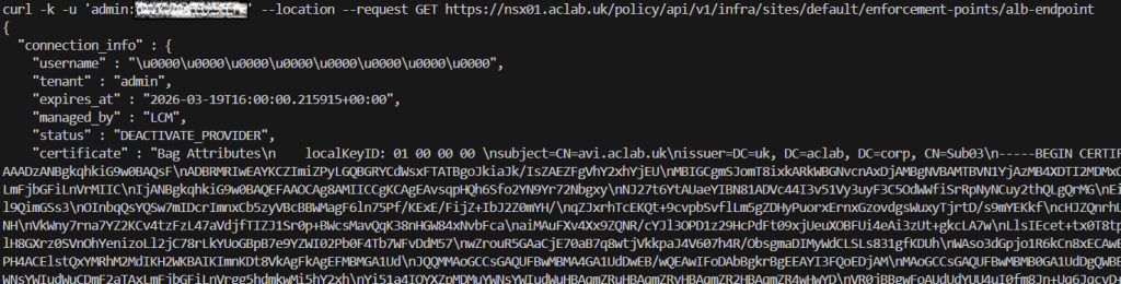
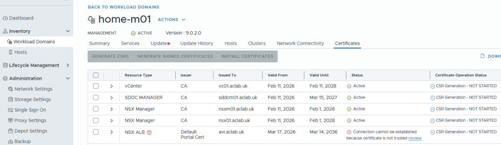
Once the certificate has changed, in SDDC manager > Inventory > Workload Domains > Select workload domain > Certificates. As we did the prep work for the trust, the NSX ALB section will show updated and the static Active.

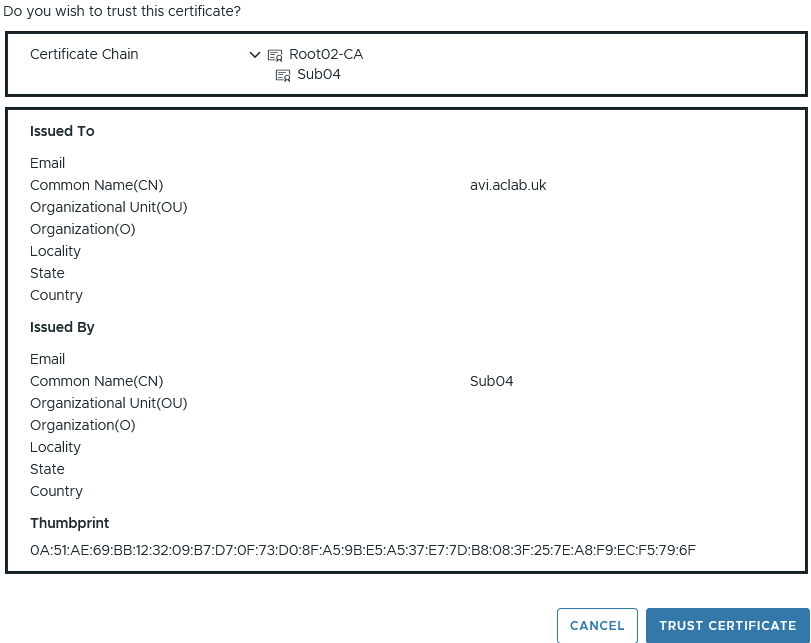
Had we not completed the trust configuration, the connection would have shown as below. We would have to click Review, then manually trust the chain, as shown below.
Configure IPAM and DNS Profiles
Next, from templates > IPAM/DNS Profiles, create a basic IPAM profile. Ignore networks and clouds for now. Click save.

Also, create a basic AVI DNS profile. Set the domain name to a subdomain. This will be used via a DNS delegation later. The default TTL is 30 seconds, making DNS cache short-lived. Click save.

They will then both show.

Tweak System-DNS Profile
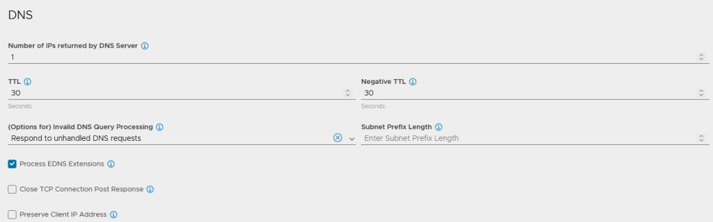
From templates > profiles > application > edit the System-DNS profile.
Change the options for invalid DNS query processing to “Respond to unhandled DNS requests” this will speed up DNS resolution by responding to DNS clients with an NOERROR response for invalid requests, i.e. when a client asks for a IPv6 AAAA address but there are only IPv4 adresses available.
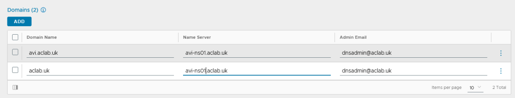
Under domains add start of authority records for the domains which we will be hosting on the AVI.
Configure NSX Cloud for NSX VPC Networking
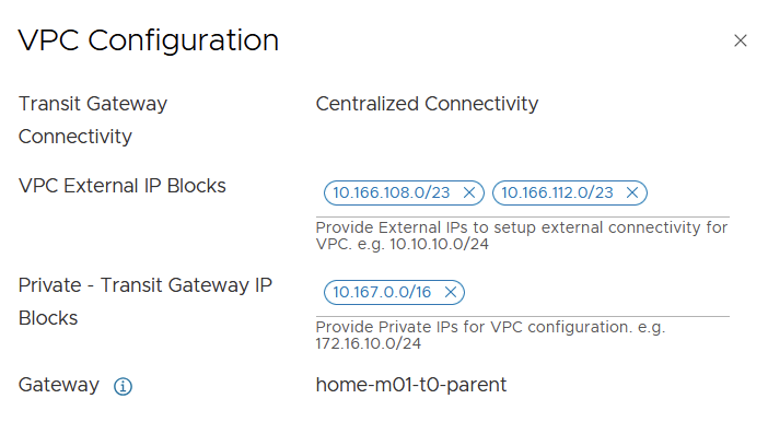
This guide assumes a basic VPC centralised connectivity networking setup is complete as per the NSX networking section of the VCF9 Lab article. When completing the steps, ensure you select active/passive for the edge cluster, as this is the only supported route for Tanzu with VPC networking
Additionally, ensure that there is sufficient capacity in the VPC external IP blocks to accommodate everything for this article. We will be deploying public routable VKS pod CIDRs, which will require an entire /24 per node. As such, a second /23 is added as per below. Should your cluster have more than two nodes, make sure you allocate a CIDR with enough capacity.
Configure AVI Tier-1 Router and Segments
From NSX Manager, create a tier-1 gateway for AVI, attach it to the tier-0 gateway, edge cluster and enable connected segment route advertisement.

Create an AVI management server segment and attach it to the AVI tier-1 gateway. This will be used for the management NIC of each of the deployed service engines.

Click edit DHCP configuration, then click the three little dots next to DHCP profile and create a new profile. Click save.

Then enter the DHCP scope details and click apply and save.

Repeat the process again for an AVI virtual server segment. I have allocated a /24 CIDR, which will allow for more than enough virtual server addresses for my lab environment.
We will only be using this subnet for an AVI DNS listener to automatically resolve addresses from deployed virtual servers; it can also be tied into GSLB if you have more than one AVI deployment spread across various geographies. Or any other infrastructure services you need load balancing for.


These are the two segments we need to complete the deployment.

Configure NSX Cloud
From the AVI control plane, go to Infrastructure > Clouds and create a new NSX cloud.

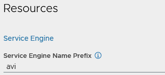
Under General, enter a name and object prefix. I don’t have or want IPv6, so I have disabled it.
If you disable DHCP here, it will break any AVI attachments that rely on DHCP; leave it enabled, as we are leveraging DHCP throughout.

Under NSX, click Change credentials. Enter the FQDN and select the pre-existing credential. Click connect.

For the management network, select the pre-created management segment we added earlier. Then enable VPC mode.

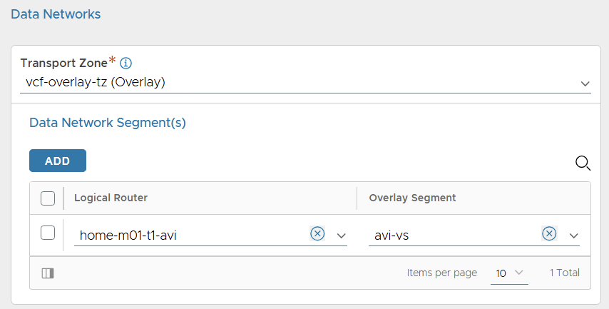
For the data network, select the vcf-overlay-tz transport zone and add the avi tier-1 gateway and avi-vs segment only.
Click add for vCenter servers, click change credentials, enter the address and use the existing credentials. Select the content library which already exists in the environment. Click done.

Select the existing IPAM and DNS profiles. Then add a DNS resolver, entering the DNS server address. Click save to complete the cloud configuration.

After a short while, the cloud static icon will turn from In Progress to Ready.

If you go to operations > events > All events, you can see what’s occurring.

Configure Service Engine Group
From the AVI control plane, go to Infrastructure > Cloud Resources > Service Engine Group > select the cloud we created earlier and edit the Default-Group. This is the shared group which is used for all service engines deployed across the NSX Project. Each NSX project will get its own AVI tenancy.
This is different to NSX Classic with AVI, in which it becomes the template from which the Tanzu supervisor service engine groups are cloned.

Modify the placement settings.
- Configure the control plane to have enough service engines for your environment. In my lab, I have 2 active service engines with 1 in reserve for HA failover capacity. Read this article to understand what kind of performance to expect from the service engines.
- Enable service engines to self-elect without the control plane.
- Enabled distributed placement, meaning the virtual servers will spread across all available service engines, rather than using additional service engines only when the max virtual server value is reached, which is by default 4. This means we spread the load across the SE pool immediately for linear scaling and better performance.

You can also prefix the AVI service engines for easier visibility. This will link up with the object prefix on the cloud, the final prefix will be m01_avi, i.e. the service engine will become m01_avi-se-<5 random letters>
Everything else can remain default; click save.
Configure NSX Cloud Networks
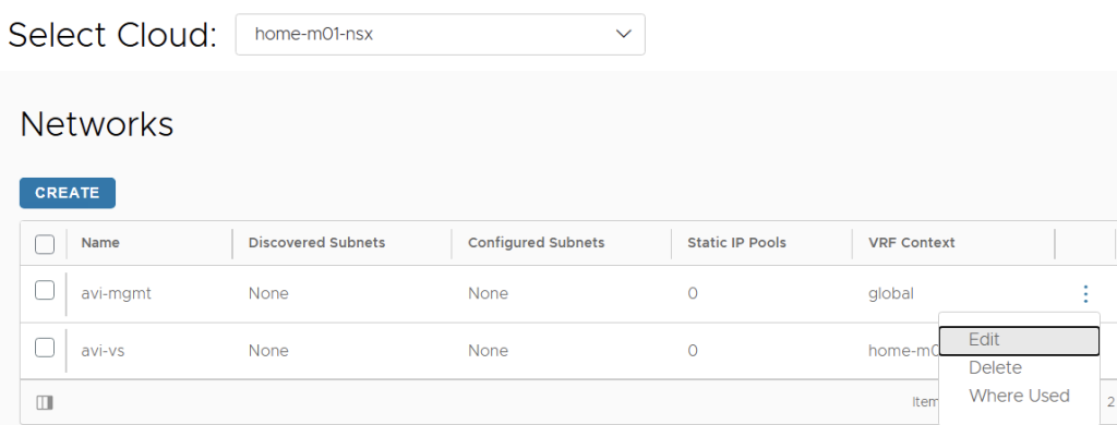
Next, we will create the IP pools. To do this, go to infrastructure > cloud resources > networks > select the NSX cloud. Edit the management VLAN segment network.
Click to add a subnet prefix, untick the use static IP address for VIP and SE, and leave the IP address range empty so DHCP is used.
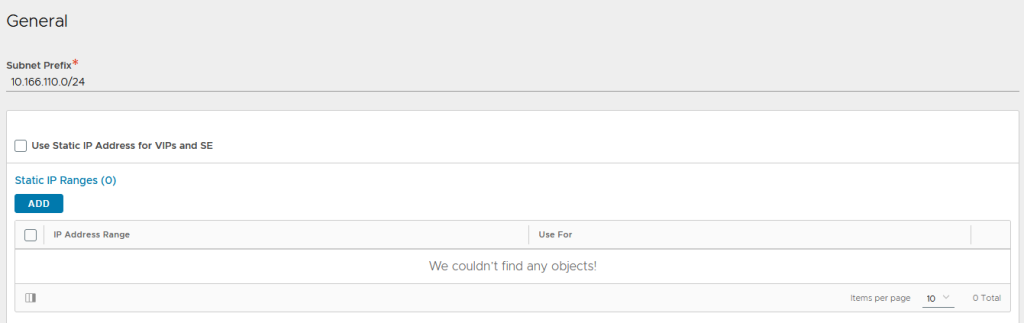
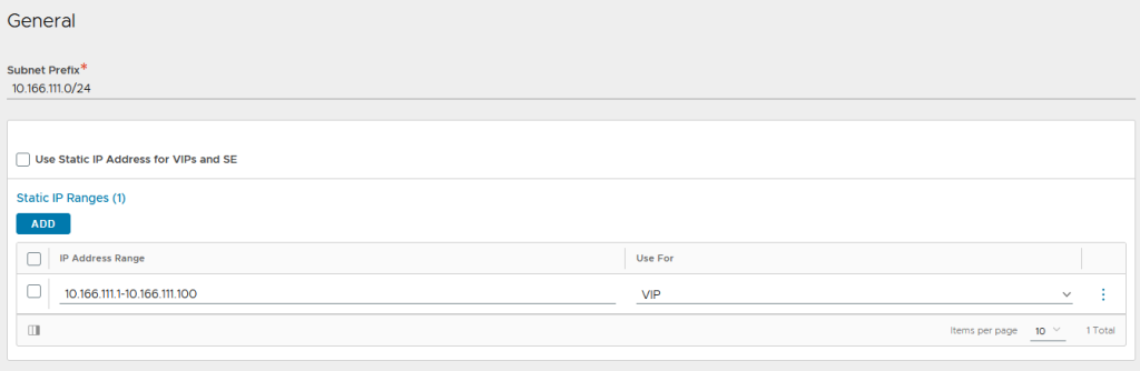
For the VS subnet, untick “use static IP address for VIPs and SE,” then add a static range. If we don’t do this, then you’ll get an error when configuring the DNS listener.
Configure AVI DNS Listener
Next, we will create a DNS virtual server to act as a listener for the avi.aclab.uk subdomain we added to the DNS profile earlier. This is the address we will forward requests to from the internal network, so we can automatically resolve virtual servers created in the AVI load balancer.
Go to application > virtual services > create virtual service > advanced setup.

Give the virtual server a name, i.e. dns-avi-listener-vs. Select DNS as the application type and use the default System-DNS profile.

Under cloud infrastructure, click the Set cloud and VRF button and then set the NSX cloud and T1-AVI VRF context.

Set the Default-Group service engine group.

Under Services, click Create on the three dots.

Add a VIP and select the avi-vs network and subnet. Click save.

Click add on DNS and enter DNS as the name. This will become “adns.avi.aclab.uk” aka authoritative DNS. Click save.

Give the virtual server a coherent name, i.e, dns-avi-listener-vs-vip. Click save to go back to the virtual service page.

Under advanced network settings, enable ignore network reachability constraints. Click save.

This will kick off the SE deployment in vSphere for this service engine group.

They will deploy to an AviSeFolder. If you want to change this, edit the default SE group, add a vCenter server and specify the folder name.

The service engine VMs will be homed to the AVI management network and virtual server network.
Once the service engine has deployed and is connected to the control plane, the virtual server in AVI will go yellow and eventually green.

Under administration > system settings > edit > DNS services. Bind the DNS virtual server we just created. Click save.

We can see the VIP segment advertised, and the virtual server responds to pings.

Deploy the Tanzu Supervisor
Before we deploy the Tanzu supervisor, we will create a VPC subnet for the service engine management network. This subnet will only host the supervisor nodes and Kubernetes API VIP, so the maximum required addresses are 5.
As we want to reuse the same JSON file from the previous Tanzu VPC stand-up article. We will create a 10.166.108.128/27 public VPC subnet called tanzu-mgmt with DHCP enabled. This will align with the JSON criteria of the last deployment.

We must exclude the first usable address in this segment for the Kubernetes API VIP. The first two addresses are used for the gateway and the DHCP server address; therefore, we will exclude 10.166.110.131. If we don’t do this, the first supervisor node comes up on the same address as the VIP, and the cluster won’t deploy properly.

We add a DNS record on my MikroTik router to match the floating VIP for the Kubernetes API.
/ip dns static set address=10.166.108.131 comment="Tanzu Supervisor VIP" name=sup01.aclab.uk type=ANow that everything is plumbed in, we can deploy the NSX VPC supervisor. As we kept the same settings as the last deployment, we can reuse the JSON file from the Tanzu with VPC Networking and NSX Load Balancer article.
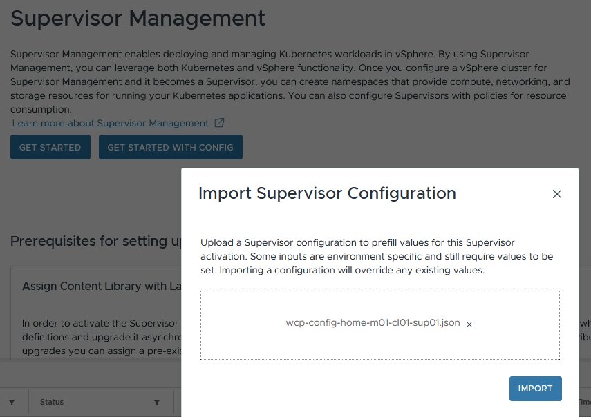
Click next, next… and complete the deployment. Then sit back and watch the deployment complete. This time around, the AVI will be configured with the Kubernetes API VIP’s, not the NSX advanced load balancer.


Validate the Tanzu Supervisor
With Tanzu VPC and AVI, there are two additional default supervisor load-balancing VIPs compared with Classic NSX.
- Kubernetes API
- Image Proxy and CLI Download Page
- vSphere Container Storage Interface
- Docker Registry – this is not present with AVI NSX Classic deployment.
- Core DNS – this is not present with AVI NSX Classic deployment.

They are all allocated from the VPC External IP Blocks CIDR as part of the deployment, which resides in NSX, not AVI. The configuration does not appear within the AVI NSX Cloud networks under infrastructure > cloud resources > networks.

As there is no corresponding network in AVI, to investigate, we can edit one of the virtual servers to take a look. The virtual servers are attached to a new VRF context that relates to the new VPCs, which are created as part of the stand-up.

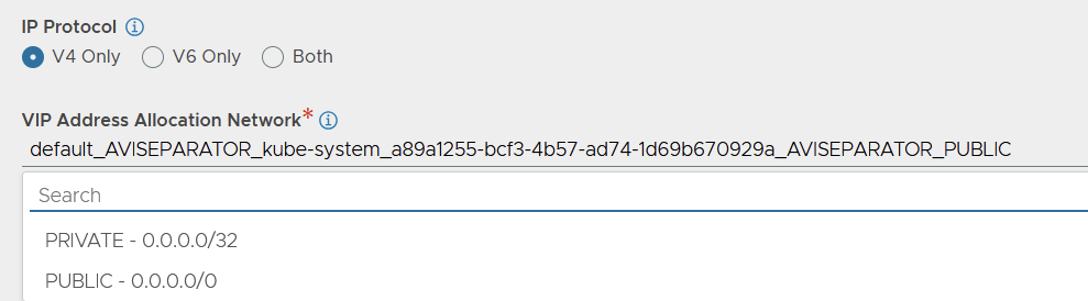
If you edit the VIP, you see the AVI network name used for the VIP allocation.

If you drop down the VIP address allocation network, the selected network is not in the list; there are just two PRIVATE and PUBLIC entries, which also do not show under the normal place in the GUI.
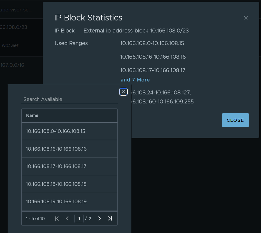
The AVI IP VIP allocation actually comes from the NSX external IP address blocks. You can see the allocations from Networking > IP Management > IP Address Pools > Edit the external address block > view statistics on the right.

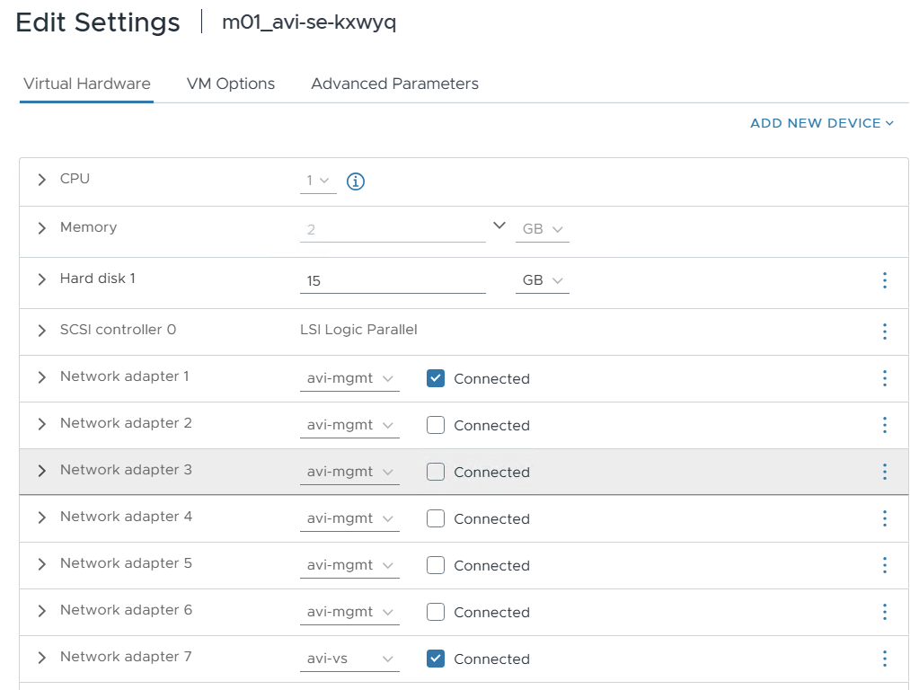
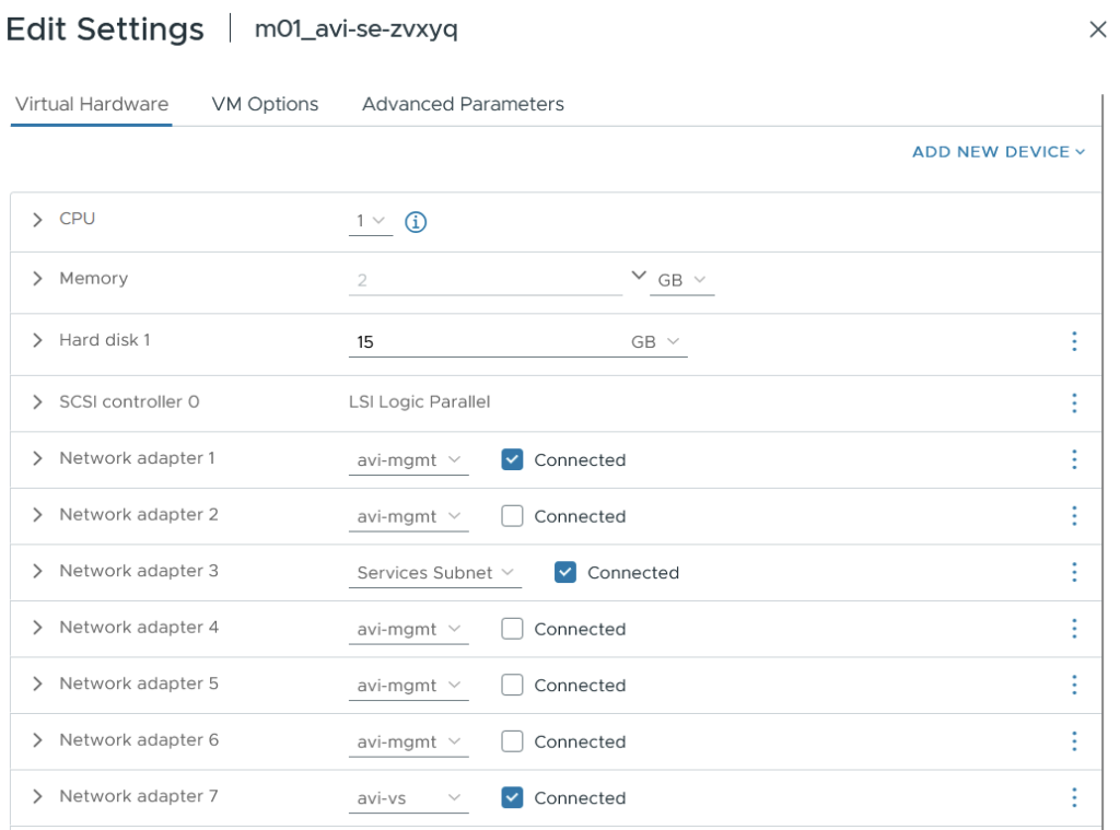
The service engines themselves share the same default service engine group (per NSX Project) and are therefore attached to multiple networks. This is different to NSX Classic, which clones a new SE group per supervisor. In total, there are three attachments; more will be added as the system grows with new VKS clusters in different namespaces. The three network attachments are.
- “avi-mgmt” VPC subnet for the supervisor VIPs.
- “Services Subnet” VPC subnet in the same VPC as the supervisor nodes. This subnet has access to the supervisor overlay network and is also an entry point for clients to reach the VIP.
- “avi-vs” segment attached to the Tier-1 gateway in NSX. This is for the DNS services VIP.
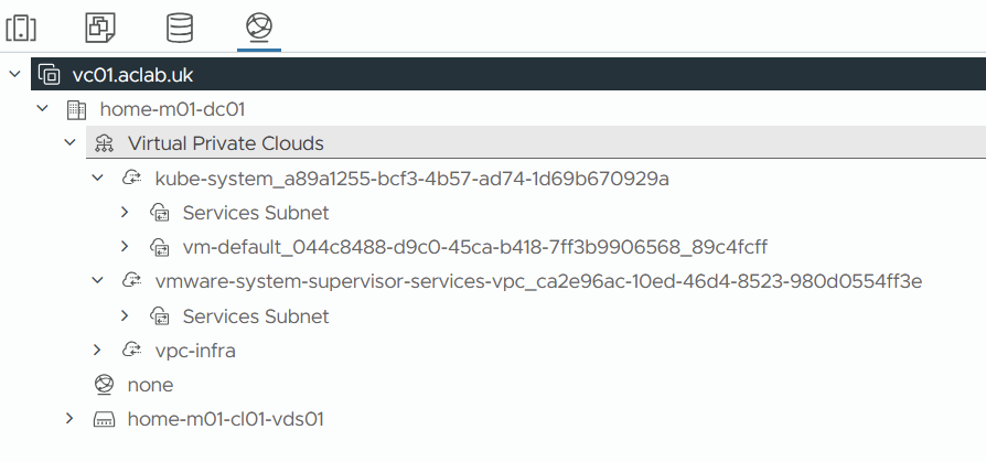
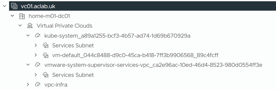
Within the AVI, there is a VRF mapped to each VPC created by the supervisor creation process.

You can see how these map by looking at the VPC list in vSphere.

Each VPC and subsequent namespace has a “Services Subnet” which forms both the front-end client and backend server data paths. Please review the topology diagram at the beginning of this article to help visualise this.
Each VPC has an SNAT rule with an address allocated from the VPC External IP Blocks CIDR.

This is what the topology looks like from an NSX VPC perspective. Remember, in addition to the below, we also have a traditional Tier-1 Gateway with an avi-mgmt and avi-vs segment for the service engines management NIC and DNS service VIP.

We deployed the AVI control plane nodes via SDDC manager into the VCF virtual machine management VLAN. The AVI services engines were deployed into an NSX Segment attached to a new Tier-1 gateway. Hence, the management connectivity path for the service engines to check in with the control plane is as follows.
- AVI Management NSX Segment
- AVI Tier-1 Gateway
- Tier-0 Gateway
- MikroTik Router via BGP
- VMware Cloud Foundation Virtual Machine VLAN 101
There is a static route for the AVI DNS services VIP on the AVI Tier-1 Gateway.

For the Supervisor kube-system VPC Gateway, static routes are created and advertised for each VIP.

NSX then advertises these via BGP to the underlay. Here is an example of the Kubernetes API VIP.


If we dig a little deeper inside the NSX edge, you can see routes for the VIPs via the service engine hosting it.

10.168.0.7 is the service engine service subnet interface address attached to the “Services Subnet”.

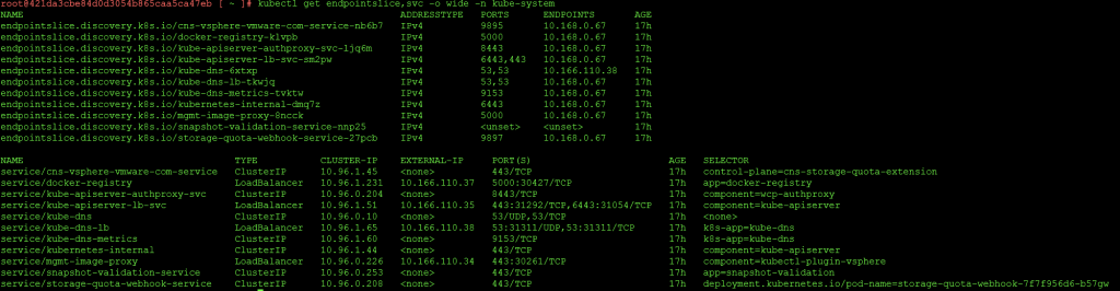
As with classic networking, NSX still retains its distributed load balancer for internal cluster IP’s.
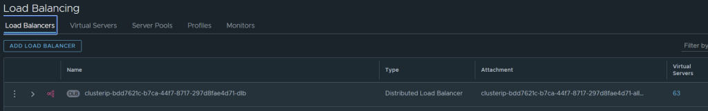
The distributed load balancer is used for Kubernetes services of type ClusterIP within the Supervisor cluster.

The server pool members are all within the 10.168.0.0/16 network, which we designated as the “nsxVpcPrivateCidrs” network in the Supervisor JSON file.

This is a /28 private VPC subnet allocated from this broader 10.168.0.0/16. This is used purely for internal communication within Kubernetes. It’s where eth1 attaches to the supervisor nodes

You can map these to the services inside Kubernetes by looking at services and endpoint slices.
Additional Namespaces
For every new namespace in the supervisor cluster, the following is added.
- A dedicated VPC with a /26 private “Services Subnet” with gateway connectivity and DHCP enabled. This is carved out of the broader “nsxVpcPrivateCidrs” 10.168.0.0/16, which we assigned in the supervisor JSON spec. This is where the static routes point to for the VIPs and also how the VIP reach the pods/nodes.
- A VRF Context within the AVI load balancer referencing the new VPC.
- A VPC Gateway linked to the shared transit gateway in the NSX project.
- A SNAT rule to hide private subnet traffic behind an address allocated from the VPC External IP Blocks CIDR.
- Each additional namespace shares the default AVI service engine group for the associated NSX cloud and tenancy.
AVI DNS Setup
We want to be able to resolve virtual services that have an associated DNS record. To make this work within the lab in an integrated way, we need to delegate the zone “avi.aclab.uk” from our primary DNS server to the AVI DNS listener VIP. We can do this on MikroTik or within Active Directory.
For the initial test, I added a static DNS record to the AVI ADNS VIP.

For MikroTik, we add the following configuration. This will forward anything within “avi.aclab.uk” to the AVI authoritative DNS VIP.
## add a forwarder for the avi dns vip
/ip dns forwarders add dns-servers=10.166.110.1 name=avi-adns-vip verify-doh-cert=no

## add a fwd record, linking it to the forwarder
/ip dns static add comment="AVI ADNS Delgation" forward-to=avi-adns-vip name=avi.aclab.uk type=FWD
For Active Directory, we can add a delegated DNS zone to the primary zone.
## add a dns record to use for the delegated name server
Add-DnsServerResourceRecordA -Name avi-adns-vs -ZoneName corp.aclab.uk -IPv4Address 10.166.110.1

## add the primary dns zone
Add-DnsServerPrimaryZone -Name aclab.uk -ReplicationScope forest

## delegate the avi subdomain
Add-DnsServerZoneDelegation -Name aclab.uk -ChildZoneName avi -NameServer avi-adns-vs.corp.aclab.uk -IPAddress 10.166.110.1

## test
nslookup test.avi.aclab.uk

Or we can add a conditional forwarder.
## add a delgated conditional forwarder
Add-DnsServerConditionalForwarderZone -Name avi.aclab.uk -ReplicationScope forest -MasterServers 10.166.110.1
nslookup test.avi.aclab.uk

## test
nslookup test.avi.aclab.uk

Deploy vSphere Kubernetes Service
Next, we need to deploy VKS services, which are the guest-based Kubernetes clusters. The supervisor is the management cluster, and the VKS clusters are the workload clusters. They have their own control plane with a unique etcd and dedicated workers.
Upgrade Supervisor Services
Ensure you are running VKS services v3.6.0. If you’re unsure how, please follow the instructions in my other VPC article.

Deploy VKS Namespace
We need to create a namespace to host the VKS clusters. You can create multiple of these and give granular permissions to each, or, for example, have a single shared one. In my lab, I have a shared “vks-clusters” namespace to which all VKS clusters are assigned. There are plenty of design options you can explore in my Tanzu Fundamentals article.
From supervisor management > namespaces > click new namespace.

Select the supervisor

Enter a DNS conformant name; you can override the networking here to pick another VPC or create a new one with a particular subnet size. In our case, we are just accepting the defaults.

Review the settings and click finish

This will create a new VPC, private services subnet with gateway connectivity, SNAT rule and VRF on the AVI Load Balancer.


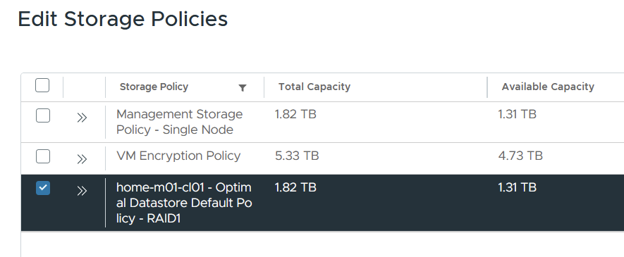
Go to supervisor management > click the vks-clusters namespace. On the summary page, add storage and select the VCF storage policy.
From the VM service tile, click Add VM class. These are the allowed sizes for the VKS nodes. In my lab, we will be using best effort small.

VKS Deployment Paths
Now we want to deploy the VKS clusters; we will be installing three to showcase various pathways.
| Pathway | Description |
| Default Antrea CNI with no-SNAT and No Encapsulation, pods will use a public VPC subnet Download YAML Specification | With this option, pods are routable by way of static routes created on NSX VPC Gateway, pointing at eth0 on each Kubernetes node. We are assigning pods into a public VPC subnet, so routing only from other VPCs and is advertised to the external network via the transit gateway and tier-0 gateway. |
| Routed Antrea CNI with no-SNAT and No Encapsulation, pods will use a private VPC subnet Download YAML Specification | With this option, pods are routable by way of static routes created on NSX VPC Gateway, pointing at eth0 on each Kubernetes node. We are assigning pods into a private VPC subnet, so routing only works inside the VPC. |
| Default Antrea CNI with SNAT and Encapsulation Download YAML Specification | With this option, pods are not routable; instead, the AVI load balancer service engine will attach to the private VPC services subnet and will get to services inside VKS using NodePort. |
Connect to VKS Cluster Namespace
Log in to the supervisor and connect to the vks-clusters namespace we just added.
## create a context for the supervisor and switch to the vks-clusters namespace.
vcf context create sup01 --endpoint sup01.aclab.uk --username administrator@vsphere.local --insecure-skip-tls-verify
vcf context use sup01:vks-clusters
Deploy All VKS Types
Once in the vks-cluster namespace, create the VKS clusters. First, enter the folder where all three YAML files are, then simply run this one command, which will apply all YAML files in the directory.
kubectl apply -f .
Give it some time, and all three clusters will be deployed. The control plane nodes are deployed, and then the worker node joins each cluster.

Three private VPC subnets will be added alongside the existing services subnet.

Static routes will exist in the VPC Gateway for the two VKS clusters with routed pods and also for each AVI Kubernetes API VIP. Below shows routes to private subnets and public subnets, which are the two routed pod variations we deployed.

The /32 routes marry up with the AVI VIPs.

Below shows the Kubernetes API virtual service for Default Antrea CNI with no-SNAT and No Encapsulation. In general, on this cluster, pods are on a routable use a public VPC subnet.
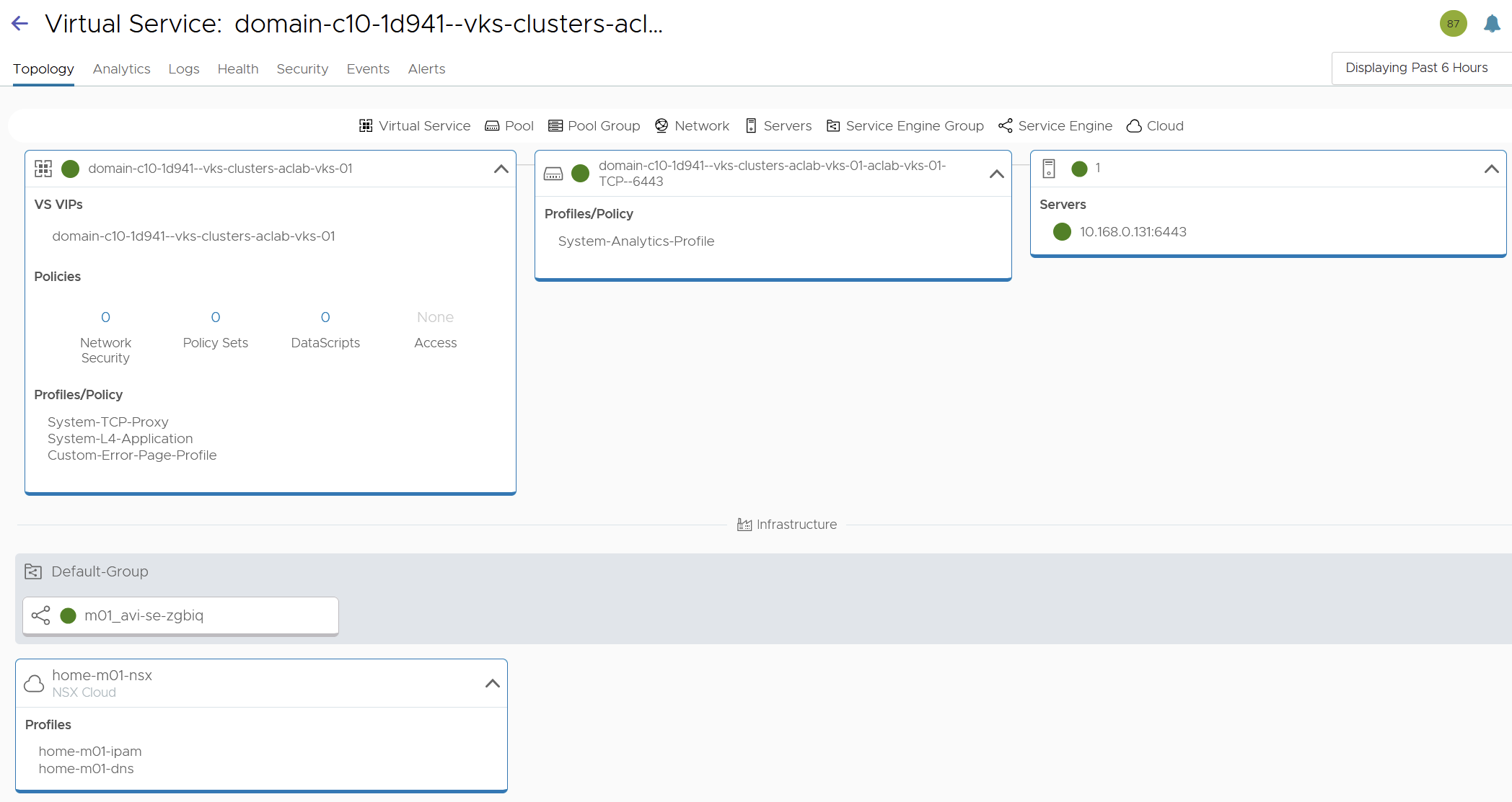
Below shows the Kubernetes API virtual service for Routed Antrea CNI with no-SNAT and No Encapsulation. In general, on this cluster, pods are on a routable private VPC subnet.

Below shows the Kubernetes API virtual service for Default Antrea CNI with SNAT and Encapsulation. In general, on this cluster, pods are on a non-routable overlay network inside the VKS cluster nodes.

Connect to each VKS Cluster
Next, log in to each VKS cluster by creating the relevant contexts.
vcf context create aclab-vks-01 --endpoint sup01.aclab.uk --username administrator@vsphere.local --insecure-skip-tls-verify --workload-cluster-name aclab-vks-01 --workload-cluster-namespace vks-clusters

vcf context create aclab-vks-02 --endpoint sup01.aclab.uk --username administrator@vsphere.local --insecure-skip-tls-verify --workload-cluster-name aclab-vks-02 --workload-cluster-namespace vks-clusters

vcf context create aclab-vks-03 --endpoint sup01.aclab.uk --username administrator@vsphere.local --insecure-skip-tls-verify --workload-cluster-name aclab-vks-03 --workload-cluster-namespace vks-clusters
Once done, you will have a context for the supervisor namespace and another for the VKS cluster itself.

Validate Antrea Routed Pods with a Public Subnet
To log in, run the following command.
vcf context use aclab-vks-01:aclab-vks-01You can validate the pod networking CIDR by running the command below. This returns the CIDR for each node, the subnet shown aligns to the VPC External IP Blocks and VPC gateway static route, which is correct as this VKS cluster YAML spec is configured for routed pods with a VPC public subnet.
Make sure you have enough capacity in the VPC External IP Block CIDRs; each node will consume a /24.
kubectl get nodes -o yaml | grep podCIDR:
As it’s public, the subnet is exposed to the external network via the VPC gateway > Transit Gateway and Tier-0 Gateway. The route table on my MikroTik router has paths to each of the external IP’s on each NSX edge in the Tier-0 edge cluster. The passive edge will prepend its AS three times, so only the active edge will be used for routing.

The static routes are advertised because the route redistribution policy in NSX has static routes added against the BGP protocol.

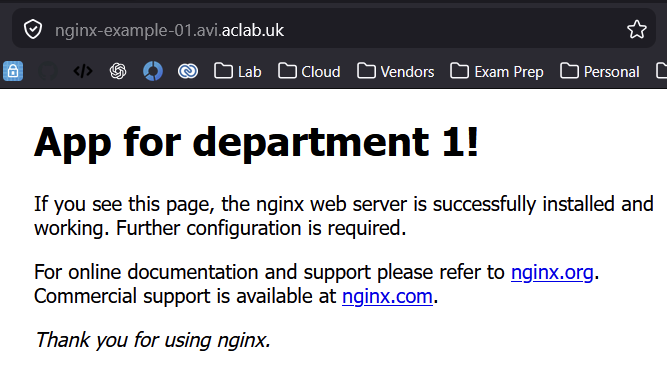
At this point, we can deploy a basic application, for example, a minimal nginx unprivileged deployment, which will work with a restricted pod security policy. Once deployed, grab the pod addresses.
## deploy application
kubectl apply -f nginx-unprivileged-minimal.yaml

## grab the pod address
kubectl get pods -n app01-dev -o wide
From my machine outside of NSX, I can connect directly to the pod that is running. This shows that routable pods work. There is no encapsulation or source NAT required, as NSX is handling routing.

Note, the second pod, which is pending, is intentional; if you look at the YAML manifest, there is pod anti-affinity configured, which will only schedule the pod if on different nodes. Given that I only have one node, we only have one pod scheduled. If you run the below, you will see what is going on.
## note the pod is spawned from a deployment so the numbers at the end will be different in your environment
k describe pod -n app01-dev nginx-example-01-55f4b6b897-4g8np
Validate Antrea Routed Pods with Private Subnet
To log in, run the following command.
vcf context use aclab-vks-02:aclab-vks-02You can validate the pod networking CIDR by running the command below. This returns the CIDR for each node; the subnet shown aligns to the Private VPC IP CIDRs, which is correct as this VKS cluster YAML spec is configured for routed pods with a VPC private subnet.
kubectl get nodes -o yaml | grep podCIDR:
As it’s private, the subnet is not exposed to the external network and is only routable within the VPC itself.

Static routes exist in the NSX VPC Gateway for the intra-VPC traffic to reach the pods. This includes the AVI service engines.

At this point, we can deploy a basic application, for example, a minimal nginx unprivileged deployment, which will work with a restricted pod security policy. Once deployed, grab a pod address.
## deploy application
kubectl apply -f nginx-unprivileged-minimal.yaml

## grab the pod address
kubectl get pods -n app01-dev -o wide
From my machine outside of NSX, I cannot connect. To reach the application, we either need to be inside the vks-clusters VPC or plumb in external connectivity. To do that quickly, we can patch the service to be of type LoadBalancer, which will create L4 connectivity via the AVI load balancer.
A better route would be to set up Gateway API or Ingress, which will also attach to a load balancer, but at Layer 7. I will say more on this later; for now, we can run the below to connect at L4 via AVI.
## expose the service using NSX load balancer
kubectl patch svc nginx-example-01-svc -n app01-dev -p '{"spec": {"type": "LoadBalancer"}}'

## confirm an external IP is allocated from NSX
kubectl get svc -n app01-dev
As you can see, an address has been assigned from the VPC External IP Blocks. A mapping is made using NodePort, which you can tell due to the high port number. The default Kubernetes node port range is 30000-32767. NodePort will cause Kube-Proxy to create an iptables DNAT on the Kubernetes nodes to pass TCP port 31878 to 80.

This is correlated on the AVI load balancer, which maps 10.166.108.27:80 to 10.168.0.68:31878. This then NAT’s on the node to the service, ultimately reaching the pod.

Hit this address via an external browser on HTTP 80, and it will connect.

You may have noticed that the pod port in the prior example is 8080, and now the service is 80. This is because the service object is on 80, which connects to the pod on 8080.

Note, the second pod, which is pending, is intentional; if you look at the YAML manifest, there is pod anti-affinity configured, which will only schedule the pod if on different nodes. Given that I only have one node, we only have one pod scheduled. If you describe the pending pod, you will see what is going on.
Validate Antrea Encapsulated Pods
To log in, run the following command.
vcf context use aclab-vks-03:aclab-vks-03You can validate the pod networking CIDR by running the command below. This returns the CIDR for each node; the subnet shown aligns to the cidrBlocks spec inside the VKS YAML.
kubectl get nodes -o yaml | grep podCIDR: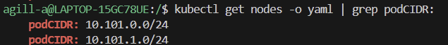
As this is technically a GENEVE overlay network within the Kubernetes nodes, the subnet is not exposed to the external network and is only routable within the Kubernetes cluster itself. No static routes exist in NSX.

At this point, we can deploy a basic application, for example, a minimal nginx unprivileged deployment, which will work with a restricted pod security policy. Once deployed, grab a pod address.
# deploy application
kubectl apply -f nginx-unprivileged-minimal.yaml

## grab the pod address
kubectl get pods -n app01-dev -o wide
From my machine outside of NSX, I cannot connect. To reach the application, we either need to be inside the Kubernetes cluster or plumb in external connectivity. To do that quickly, we can patch the service to be of type LoadBalancer, which will create L4 connectivity via the NSX load balancer.
A better route would be to set up Gateway API or Ingress, which will also attach to a load balancer, but at Layer 7. I will say more on this later; for now, we can run the below to connect at L4 via NSX.
## expose the service using NSX load balancer
kubectl patch svc nginx-example-01-svc -n app01-dev -p '{"spec": {"type": "LoadBalancer"}}'

## confirm an external IP is allocated from NSX
kubectl get svc -n app01-dev
As you can see, an address has been assigned from the VPC External IP Blocks.

The AVI VIP is deployed as follows, with an address from the VPC External IP Blocks. A mapping is made using NodePort, which you can tell due to the high port number. The default Kubernetes node port range is 30000-32767. NodePort will cause Kube-Proxy to create an iptables DNAT on the Kubernetes nodes to pass TCP port 31889 to 80.

Hit this address via an external browser on HTTP 80, and it will connect.

You may have noticed that the pod port in the first example is 8080, and now the service is 80. This is because the service object is on 80, which connects to the pod on 8080.
Note, the second pod, which is pending, is intentional; if you look at the YAML manifest, there is pod anti-affinity configured, which will only schedule the pod if on different nodes. Given that I only have one node, we only have one pod scheduled. If you describe the pending pod, you will see what is going on.
AVI Kubernetes Operator
We can also integrate AKO for Ingress. I will go into more detail on this subject in a dedicated article. For now, here is a basic configuration for NSX VPC with routable pods. The helm values file for AKO is here. A very basic ingress object to confirm behaviour is here.
# switch to the routed public pod vks cluster
vcf context use aclab-vks-01:aclab-vks-01

# deploy ako
helm upgrade --install avi-ako oci://projects.packages.broadcom.com/ako/helm-charts/ako --version 2.1.3 -f nsx-vpc-values.yaml --set avicredentials.password=<avi-ctrl-password> --namespace=avi-system --create-namespace
helm list -n avi-system
k label ns avi-system pod-security.kubernetes.io/enforce=baseline

# deployment confirm
k get pods,sts,deploy -o wide -n avi-system
k logs -n avi-system ako-0 -c ako
k logs -n avi-system ako-0 -c ako-gateway-api
k get ingressclass

## deploy basic ingress
k apply -f nginx-unprivileged-minimal-ingress.yaml
This attaches to the AVI load balancer on 10.166.108.29 using a shared virtual server. The server endpoint is available via a pool group and application domain name referencing the ingress FQDN. The back-end server for the FQDN is 10.166.112.2:8080, which is a routable pod address. This is an optimal path that requires no NAT.


When I connect via a browser, the name is automatically resolved by the forwarder we set up earlier on my Active Directory domain controller.
Deploy vSphere Pod Application
If we switch to the supervisor and deploy the application, we can see vSphere pods in action. For this, I created a “app01-dev” namespace in the supervisor, then ran:
# switch context to the supervisor vks namespace
vcf context use sup01:vks-clusters

# deploy the sample application
k apply -f nginx-unprivileged-minimal.yaml
The new namespace has the normal private services subnet, and for vSphere pods, a private transit gateway subnet is created. This means the pods are routable inside the NSX project via the transit gateway, but not outside in the external network.

As this is vSphere pods, they show in vSphere, and the containers execute in a CRX virtual machine.

The pod is directly accessible from another virtual machine running in the same NSX project, which is connected to the same transit gateway.

The supervisor cluster has no IngressClass; you can check this via the supervisor node as root.

However, the AKO operator is deployed into the vmware-system-ako namespace and is watching for ingress objects. This is detailed in the documentation here. There is a deployment with a manager and an infra container inside the pod.

You can check the AKO container logs using the commands below.
k logs -n vmware-system-ako deploy/vmware-system-ako-ako-controller-manager -c infra -f
k logs -n vmware-system-ako deploy/vmware-system-ako-ako-controller-manager -c manager -f
We can connect to the application to the external network at either L4 using a service of type LoadBalancer or at L7 using an Ingress object. For layer 4, we can patch the service to type LoadBalancer.
k patch svc nginx-example-01-svc -n app01-dev -p '{"spec": {"type": "LoadBalancer"}}'
k get svc,pods,endpointslice,nodes -n app01-dev -o wide
This correctly attaches to the AVI with direct access to the pod address, as the Service Engine is plumbed into the Services Subnet in the same VPC. This means there is no NAT, and the routing path is optimal.

For L7 connectivity, we need to deploy an ingress. There is a basic manifest in GitHub that we can use. If we do that whilst also watching the infra container logs, we can observe the behaviour.
## capture the infra container logs, run from a supervisor node
k logs -n vmware-system-ako deploy/vmware-system-ako-ako-controller-manager -c manager -f

## patch service back to ClusterIP
k patch svc nginx-example-01-svc -n app01-dev -p '{"spec": {"type": "ClusterIP"}}'

## deploy the ingress object to attach to the app service object
k apply -f nginx-unprivileged-minimal-ingress.yaml

## check the ingress is attached to the service and endpoints
k describe ing -n app01-dev
k get svc,endpointslice -n app01-dev

## check resolution works ok
dig +short nginx-example-01.avi.aclab.uk
If you experience issues, remember that the AVI will not work properly if you have the same host FQDN elsewhere in the same NSX tenant / AVI tenant.

From an AVI VS point of view, we have a parent-child setup with a policy set.

The parent VS is attached to the ingress on 10.166.108.32, which is an address from the VPC External IP Blocks.

The child VS has the routable podCIDR address, which is an optimal path.

We can confirm this by looking at the pod address, which returns 10.167.0.66, which is the server address on the child virtual server.
k get pod -o wide
Final Topology
The topology as a whole looks like this.
Conclusion
This concludes part #2 and the series of AVI integration with Tanzu. Next I will spend some time unpacking AVI Kubernetes Operator, as it has many flags and deployment routes.